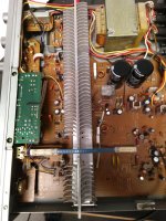
... today had some time to repair my very old Pioneer SA-710 Amplifier (got a used one around 1984 - 1985) which died after more as 35 years of daily usage.
Replaced big 56V/12000µ lytics using Panasonic THA 50V/18000µ.
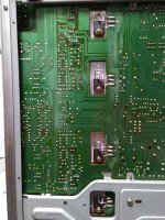
Replaced drivers
Replaced defective 0.47R emitter resistors with MPC74 - 0.47R
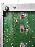
The suck out current was too low (the MG's have higher cob) so I soldered 330R parallel to R97 and R98 to double the current - now crossover distortions are at a minimum.
Added some small heat sinks for the drivers due to the higher power dissipation after suck out resistor change.
Next step is to replace all other lytics.
The switches and potentiometers need some cleaning too.
BR, Toni
Replaced big 56V/12000µ lytics using Panasonic THA 50V/18000µ.
Replaced drivers
- 2SC2275 by 2SC4793
- 2SA985 by 2SA1837
- 2SC2525 by MG6330-R
- 2SA1075 by MG9410-R
Replaced defective 0.47R emitter resistors with MPC74 - 0.47R
The suck out current was too low (the MG's have higher cob) so I soldered 330R parallel to R97 and R98 to double the current - now crossover distortions are at a minimum.
Added some small heat sinks for the drivers due to the higher power dissipation after suck out resistor change.
Next step is to replace all other lytics.
The switches and potentiometers need some cleaning too.
BR, Toni
Attachments
Last edited:
"The suck out current was too low (the MG's have higher cob) so I soldered 330R parallel to R97 and R98 to double the current - now crossover distortions are at a minimum.
Added some small heat sinks for the drivers due to the higher power dissipation after suck out resistor change".
That is the wrong way to set the Vbe voltages on the output transistors.
Adjust the voltage across D10 and D9 with a suitable value resistor or better still adjust the current with the adjustment shown in the service manual.
The voltage across TP20/21 and TP22/23 should be around 4.5mV with no load and no signal.
no! you need to compensate the higher capacitance/eleltron load of the MGs. Indeed the bias current is now low but the crossover distortion is lower as datasheet values.
The Oliver criterion is with this new suck out value meet. after some warm up the amp has about 42mv between the emitter resistors.
BR , Toni
The Oliver criterion is with this new suck out value meet. after some warm up the amp has about 42mv between the emitter resistors.
BR , Toni
Last edited:
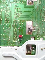
- added suck out speed up capacitor 10nF
- added VAS anti sticking diode BAV21
- changed many lytics in the amplifier signal path
- Distortion 20 - 20kHz@1W@8R below 0.04% bw. 80kHz.
- Distortion 20 - 20kHz@1W@8R below 0.02% A-w
- Distortion 20 - 20kHz@75W@8R below 0.015% bw 80
- Distortion 20 - 20kHz@75W@8R below 0.005% A-w
- SNR A-w 90dB
BR, Toni
Attachments
- Status
- Not open for further replies.