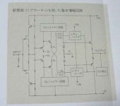
What are the mystery black boxen? 3way current mirror???
It would make sense both emitters of the diamond buffer
to operate at same current? And then also couple this same
current into the output... But thats just me thinking, I am no
translator. The middle leg would be the master and the other
two the copies...
I suspect the other black boxen are +4 and -4V regulators,
with a feature to be disabled (open circuit) to shut down
the entire amplifier.
Not a mystery, just I want to know from what amplifier is this schematics.What are the mystery black boxen? 3way current mirror???
Where did you find it? If it's in japaneese you could google-translate is wich usually gives an understandable english from japaneese.
Anyway - i studied quite some Pioneer schematics during the years, and with input fets I would think we are in the high-end category. It could one from the "Exclusive" series, or the integrated A09, A07.
Two links to get you closer:
TVK °7 : Pioneer
HiFi Engine | Download Free User/ Service Manuals, Amplifier, Receiver, CD, Tape, Tuner, Video (requires login, but its free and there are many schematics)
Some Information
"http://www.geocities.jp/bluegourdscastle/audio/amp-011.html"
Above site have the current mirror circuit informaton (fig).
And more explanation (fig) of the current mirror circuit is bellow
"http://www.geocities.jp/mason_ishiatama/kaiseki/kaiseki1/Kaiseki1-5.htm"
Regards.
"http://www.geocities.jp/bluegourdscastle/audio/amp-011.html"
Above site have the current mirror circuit informaton (fig).
And more explanation (fig) of the current mirror circuit is bellow
"http://www.geocities.jp/mason_ishiatama/kaiseki/kaiseki1/Kaiseki1-5.htm"
Regards.
The circuit is of Pioneer CZ-1(a). The mysterious boxes are covered here:
http://www.diyaudio.com/forums/soli...-super-pair-buffer-simulation-schematics.html
http://www.diyaudio.com/forums/soli...-super-pair-buffer-simulation-schematics.html
Very similar schematics you can find in Pioneer M5
And this type of topology is called Super Linear Circuit
the Headphone amplifier
http://www.diyaudio.com/forums/soli...linear-circuit-ozawa-okio-ishikawa-kikuo.html
http://www.diyaudio.com/forums/solid-state/144054-pioneer-m5.html
And this type of topology is called Super Linear Circuit
the Headphone amplifier
http://www.diyaudio.com/forums/soli...linear-circuit-ozawa-okio-ishikawa-kikuo.html
http://www.diyaudio.com/forums/solid-state/144054-pioneer-m5.html
Attachments

The Pioneer Exclusive M5 service maunal:
Pioneer M5 Exclusive Service Manual free download,schematics,datasheets,eeprom bins,pcb,repair info for test equipment and electronics
Pioneer M5 Exclusive Service Manual free download,schematics,datasheets,eeprom bins,pcb,repair info for test equipment and electronics
Last edited:
Somebody build an amplifier with SLC topology? Experiences?
A few months ago I build an Andrea´s amplifier for low power amp (<20W) with very good results but no measures.
the Headphone amplifier
A few months ago I build an Andrea´s amplifier for low power amp (<20W) with very good results but no measures.
the Headphone amplifier
- Status
- Not open for further replies.
- Home
- Amplifiers
- Solid State
- Pioneer Japanese Schematic