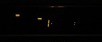
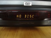
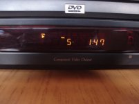
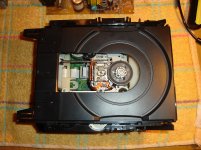
My dvd player Pioneer DV-535 does not recognize the DVD or CD when turning. Flashing light display track as I show in the attachments.
If you leave it on about 15 minutes it begins to function perfectly.
Has it happened to someone ?
Any idea where to find the fault?
Obviously a false contact, but where to look ?
Thanks in advance 🙂
If you leave it on about 15 minutes it begins to function perfectly.
Has it happened to someone ?
Any idea where to find the fault?
Obviously a false contact, but where to look ?
Thanks in advance 🙂
Attachments

🙄 Nobody has experience in repairing cd players?
I accept all kinds of opinions, even the craziest...
(You never know where the hare jumps ...) 😀
I accept all kinds of opinions, even the craziest...
(You never know where the hare jumps ...) 😀
Obviously a false contact, but where to look ?
That would actually be way down the list...
1/ Have you cleaned the lens.
2/ As its a DVD player then it probably uses a switching type power supply. Dried out electrolytic caps could be a possibility.
Hi Mooly
First, thanks for answering.🙂
Second, yes, the source is schitwing, I will control the output voltage to see if there are fluctuations.
Capacitors may be bad and the heat load assimilate something, that's what you think?
First, thanks for answering.🙂
Second, yes, the source is schitwing, I will control the output voltage to see if there are fluctuations.
Capacitors may be bad and the heat load assimilate something, that's what you think?
Yes, caps are always a favourite. Excess ripple will readily show on a scope for those performing reservoir and smoothing functions. More problematic are those in the small signal stages (servos/RF stages etc).
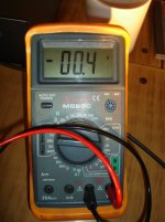
Unfortunately I can not measure the ripple due to lack of instruments, but control the voltage at collector of a transistor and is about 0.5 Volts when switched on and up about 9 volts when off.
So I put some chips to your advice and will control the source of the switched capacitors.
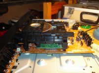
Obviously I start with the most important, the biggest one you can see in the picture.
Someone will have the circuit?
If, the laser lens has been cleaned.
*
Thank you and tell you the progress, or setbacks, I think if I mess will be a good excuse to buy an Oppo ....
So I put some chips to your advice and will control the source of the switched capacitors.
Obviously I start with the most important, the biggest one you can see in the picture.
Someone will have the circuit?
If, the laser lens has been cleaned.
*
Thank you and tell you the progress, or setbacks, I think if I mess will be a good excuse to buy an Oppo ....
Attachments
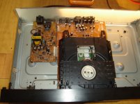
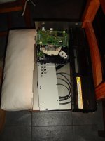
To test the power sector was not necessary to disarm them, but I struggled to understand how connections are unlocked bridges ..... help me God !, how good was working with vacuum tubes and welds point to point....😱
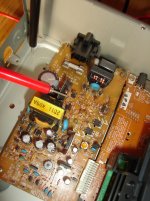
I think I've identified the culprit, this capacitor 68 x 400 is damaged, now I get the correct value, replace it and see what happens .....
I think I've identified the culprit, this capacitor 68 x 400 is damaged, now I get the correct value, replace it and see what happens .....
Attachments
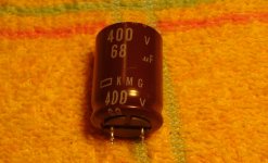


That capacitor is the main reservoir... why do you suspect that one ?
You really need proper equipment to diagnose problem capacitors, yes they are always the first things to suspect, but just changing them in hope isn't perhaps a great idea.
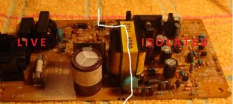
And stay safe 🙂 Everything to the left of that white line on the board is live and not isolated from the mains. Working on non isolated mains requires specialised knowledge and practices to stay safe and is outside the scope (and rules) of the forum.
If you are going to replace that cap then choose a similar high ripple, low E.S.R. high temperature component. The other electrolytic caps on the right of the board could simply be replaced (again high ripple, low E.S.R., high temperature types) and see where that gets you.
Ideally you should be looking at the secondary rails on a scope to see if there is a problem first.
(The removed cap will tend to develop a voltage across its terminals now its removed from the circuit due to 'dielectric absorption'. Because its been running at high voltage, the terminal voltage could rise to quite a high value so beware... they can bite)
You really need proper equipment to diagnose problem capacitors, yes they are always the first things to suspect, but just changing them in hope isn't perhaps a great idea.
And stay safe 🙂 Everything to the left of that white line on the board is live and not isolated from the mains. Working on non isolated mains requires specialised knowledge and practices to stay safe and is outside the scope (and rules) of the forum.
If you are going to replace that cap then choose a similar high ripple, low E.S.R. high temperature component. The other electrolytic caps on the right of the board could simply be replaced (again high ripple, low E.S.R., high temperature types) and see where that gets you.
Ideally you should be looking at the secondary rails on a scope to see if there is a problem first.
(The removed cap will tend to develop a voltage across its terminals now its removed from the circuit due to 'dielectric absorption'. Because its been running at high voltage, the terminal voltage could rise to quite a high value so beware... they can bite)
Attachments
Last edited:
Hi academia50,
Mooly is exactly right! Usually it's the small capacitors that will fail before the larger ones. You also have switch contacts that you should look at.
Equipment. If you enjoy working on projects in electronics, you should obtain an oscilloscope. They aren't very expensive these days, especially a used one in good condition. Do buy new probes for it, equal or higher bandwidth. To measure some points, you might need a 100:1 probe rather than the 10:1 people normally use.
-Chris
The big cap is a Nippon Chemicon, and it will absolutely NOT be at fault. It is the Rubycon caps in rest of supply that are to be suspected.
The very abnormal thing I see is that there is major signs of excessive heat on primary side of supply, especially around Q71. This is extremely strange. And more alarmingly, around D12, one of the main input rectifiers. It will take more work to fix this unit that it is remotely worth. It's a very cheap model with a pretty unreliable laser, and I would not recommend wasting much time/money on it.
The very abnormal thing I see is that there is major signs of excessive heat on primary side of supply, especially around Q71. This is extremely strange. And more alarmingly, around D12, one of the main input rectifiers. It will take more work to fix this unit that it is remotely worth. It's a very cheap model with a pretty unreliable laser, and I would not recommend wasting much time/money on it.
Updates:
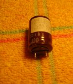
The suspect capacitor is in good condition, it was tested with the multimeter in position R (x20 K) and fluctuated reading unusual way. This was because the 9 volt battery was half-empty.
The fault is not caused by the power source so I analyze.
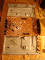
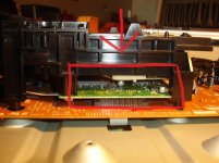
Applying heat and cold alternately, on the marked area in the picture, the fault appears and disappears.
RF capacitors? CI? The area is not accessible to the same testing element by element to identify .....😡
As stated stephensank the value of this DVD Player should not lose more time, I'll use it well (they are 15 minute warm and it works normally) and buy new, more audiophile. Oppo BD-105EU or something.
Thanks Mooly, Anatech and stephensank for their answers anyway. 🙂
The suspect capacitor is in good condition, it was tested with the multimeter in position R (x20 K) and fluctuated reading unusual way. This was because the 9 volt battery was half-empty.
The fault is not caused by the power source so I analyze.
Applying heat and cold alternately, on the marked area in the picture, the fault appears and disappears.
RF capacitors? CI? The area is not accessible to the same testing element by element to identify .....😡
As stated stephensank the value of this DVD Player should not lose more time, I'll use it well (they are 15 minute warm and it works normally) and buy new, more audiophile. Oppo BD-105EU or something.
Thanks Mooly, Anatech and stephensank for their answers anyway. 🙂
Attachments
^ It does sound to be something like that. Those aluminium surface mounted electrolytics are not beyond suspicion either.
- Status
- Not open for further replies.
- Home
- Source & Line
- Digital Source
- Pioneer DV-535 It works after a little while