Hello to the Forum,
I have on my desk a Pioneer CT-93 deck with an unstable VFD.
At the beginning it was just blinking but now it turns almosts completely off after few seconds from switch on.
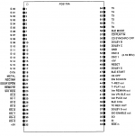
The VFD is driven by a PD3170A uC which, in turn, is controlled by a PD4290C uC

After some struggling I found that the PD4290C is stuck due to two wrong logic signals.
Instead of:


I have:
*RESET = 0V
POWER OFF is

This is the portion of power supply that generates these two signals:

R751 is fed by a 2-diodes half-wave rectifier:

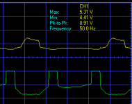
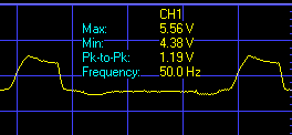
This is what I have on C751 positive pole:

and this is what's on Q751 base(yellow) and collector(green), referred to GNDC:

I have already verified C751 and it was 4.2uF instead of 4.7. Changed it, just in case, but no effect.
What's going on here??
Q751 fried?
Thank for reading and eventual thoughts.
Raf
I have on my desk a Pioneer CT-93 deck with an unstable VFD.
At the beginning it was just blinking but now it turns almosts completely off after few seconds from switch on.
The VFD is driven by a PD3170A uC which, in turn, is controlled by a PD4290C uC
After some struggling I found that the PD4290C is stuck due to two wrong logic signals.
Instead of:
I have:
*RESET = 0V
POWER OFF is
This is the portion of power supply that generates these two signals:
R751 is fed by a 2-diodes half-wave rectifier:
This is what I have on C751 positive pole:
and this is what's on Q751 base(yellow) and collector(green), referred to GNDC:
I have already verified C751 and it was 4.2uF instead of 4.7. Changed it, just in case, but no effect.
What's going on here??
Q751 fried?
Thank for reading and eventual thoughts.
Raf
Attachments
It'd take you half an our and 2 bucks worth of components to change all active components and tell us the result...It's easy to measure everything there with a cheap DMM...
I already considered that but I've had troubles in finding info on the OTC114TS.
It's cited in a load of service manuals but no evident supply sources.
It's cited in a load of service manuals but no evident supply sources.
Last edited:

It ended up that C751 was actually not connected to ground!😕
The solder was visually perfect before and after cap replacement but the issue was always there.
At one time I decided to replace the C751 with a 10uF one, in order to see what teh effect would had been. When I suctioned the solder, the copper ring around the cap followed it, showing that is was actually not connected to the line...the break appeared like a clean cut.😳
Once firmly reconnected the C751 to the GND line, the circuit started making its work!
To better understand what was going on I also decided to simulate the circuit with basic TR and Diode models.

This is how the POWEROFF signal should look like in normal conditions, starting from deck switch-on time:

The job of this piece of circuit is to keep the POWEROFF low during normal operations.
When the deck is switched off, the POWEROFF signal quickly rises to 5V rail and then starts dropping down following the slow supply caps discharge. When POWEROFF is high all the logic ICs stop their operations and disable every output, avoiding strange transient behaviours.
Hope this could help somebody one day
Cheers
Raf
The solder was visually perfect before and after cap replacement but the issue was always there.
At one time I decided to replace the C751 with a 10uF one, in order to see what teh effect would had been. When I suctioned the solder, the copper ring around the cap followed it, showing that is was actually not connected to the line...the break appeared like a clean cut.😳
Once firmly reconnected the C751 to the GND line, the circuit started making its work!
To better understand what was going on I also decided to simulate the circuit with basic TR and Diode models.
This is how the POWEROFF signal should look like in normal conditions, starting from deck switch-on time:
The job of this piece of circuit is to keep the POWEROFF low during normal operations.
When the deck is switched off, the POWEROFF signal quickly rises to 5V rail and then starts dropping down following the slow supply caps discharge. When POWEROFF is high all the logic ICs stop their operations and disable every output, avoiding strange transient behaviours.
Hope this could help somebody one day
Cheers
Raf
- Home
- Source & Line
- Analogue Source
- Pioneer CT-93 display and transistors