Hi guys,
I need some help with a pioneer SX-V300 (~1984) receiver i recently aquired 😱.
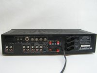
On the right channel, it sounds distorted (as if when your radio station is not tuned properly) and it happens on all input sources (CD, tape, phono, etc). The left channel appears to be fine. It is a 45Wx2 amp based on the STK4181II chip. I doubt it is the chip since it still sounds loud even with the distortion.
It would be much apprciated, if someone can shed some light on this issue. And hopeully a schematic if someone has one.
I need some help with a pioneer SX-V300 (~1984) receiver i recently aquired 😱.
On the right channel, it sounds distorted (as if when your radio station is not tuned properly) and it happens on all input sources (CD, tape, phono, etc). The left channel appears to be fine. It is a 45Wx2 amp based on the STK4181II chip. I doubt it is the chip since it still sounds loud even with the distortion.
It would be much apprciated, if someone can shed some light on this issue. And hopeully a schematic if someone has one.
Attachments

The virtue of having only one bad channel is that you have a known good reference for all your tests and measurements.
The problem with repairing a receiver is so many small parts in a confined chassis.
The problem with repairing a receiver is so many small parts in a confined chassis.
Check for DC on the output first.
My guess is it is the chip. Those STKs are famous for that kind of failure.
My guess is it is the chip. Those STKs are famous for that kind of failure.
hello.
perhaps only a (bad) contact problem.
so i would begin with cleaning all fuses,switches,potentiometers........... and the headphone jack.
greetings
perhaps only a (bad) contact problem.
so i would begin with cleaning all fuses,switches,potentiometers........... and the headphone jack.
greetings
Thanks for the input guys.
yea its hard enough getting into the main pCB with all the wiring, etc. Its one of the smallest amps i have seen.
I was thinking of checking the input pins to the STK with a small speaker and seeing if it is ditorted at the input first. And depending on how it is proceed to checking the contacts, pots, etc.
And btw, i tested it with a pair of headphones last night, and it sounds perfect on both channels. But as soon as the speaker is connected, the distortion begins from the right channel.
yes,try to clean the headphone jack,with contact spray or so........;
are there relays between the speakers and the powerchip? if so perhaps one is bad.
are there relays between the speakers and the powerchip? if so perhaps one is bad.
I forgot to mention about the headphones, when the speakers are connected BOTH the headphone right ch and sp. rch are distorted. So i doubt its the relay or anything. Got a feeling the problems withthe chip or before the chip.
Ok, I have some measurements after testing.
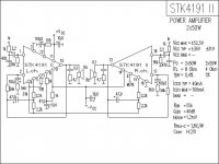
At the speaker output pins of the STK (pin 10 and 13 -- see schematic), the left channel is ok, the right ch is distorted (this rules out any problem with the headphone jack or relay or any connections).
At the input pins of the STK (pin 1 and pin 18), i measured the input with a small speaker and BOTH channels are producing sound as normal (no distortion).
So does this mean the problem is the chip or the some of the components around the chip? I was thinking of swapping pin 1 with 18 to confirm if the problem is within the chip or before. Will post results soon. Btw both pins measure 3.3V DC.
Is it possible for an STK chip to have a distorted output due to a problem within the chip? I have never heard of a chip amp having any problems other than a blown output😕. Any thoughts are much appreciated. Thanx heaps!
Attachments
Ok, I have some measurements after testing.
At the speaker output pins of the STK (pin 10 and 13 -- see schematic), the left channel is ok, the right ch is distorted (this rules out any problem with the headphone jack or relay or any connections).
At the input pins of the STK (pin 1 and pin 18), i measured the input with a small speaker and BOTH channels are producing sound as normal (no distortion).
So does this mean the problem is the chip or the some of the components around the chip? I was thinking of swapping pin 1 with 18 to confirm if the problem is within the chip or before. Will post results soon. Btw both pins measure 3.3V DC.
Is it possible for an STK chip to have a distorted output due to a problem within the chip? I have never heard of a chip amp having any problems other than a blown output😕. Any thoughts are much appreciated. Thanx heaps!
Do you have a scope? That would definitely nail it down. What you're describing is what would happen if you lost one of the 2 output devices (or emitter resistors) in the right channel. The amp can deliver normal sound to the very light load of the headphones because the drivers are sufficient for that task. Add the speaker and either the op or bottom of the signal gets mangled. Replace the STK and you'll be good.
G²
hello.
last chance..............there could be a damaged part around the stk,especially the elcos on input 2,2uf and 100uf on feedback...........or so.if you have a dmm you can measure the resistors............if all that does not work the stk should be bad.................
greetings
last chance..............there could be a damaged part around the stk,especially the elcos on input 2,2uf and 100uf on feedback...........or so.if you have a dmm you can measure the resistors............if all that does not work the stk should be bad.................
greetings
Last edited:
I swapped the two input pins (pin 1 and 18) to check if the problem is before the STK, and its always the right side output (pin 10) that has the distortion.
So i guess its definitely fault with the STK or some of the resistors/caps around it.
@mjf: i can measure the resistors with my dmm. Is there a way to check the caps?
@stratus46: i dont have a scope with me. Is there any other way to confirm the STK is at fault (may be some resistance mesurement across the output pins 10 and 13...or so)
@ dmx2020........what will you do if the stk is faulty?.............if you decide to buy a new one..........i would build in new elcos.
greets
greets
no DC at the terminals, just distortion (like its not getting enough power, or say like a badly tuned radio station)
Mjf...what do u refer to when u say "elcos"? is it the caps?
...Also pin 2 (and 17) gets an input from the 'simulated stereo' switch and other controls of the front panel. This is the (-) input to the opamps of the STK. I do not know what this is supposed to do. Is it some sort of supplementary signal input for the main signal input of pin 1 (and 18)? thanks
elco = electrolytic capacitor,the bigger (polarised) caps.........10uf,......47uf,........;
i think pin 2,17 is the input for the negative feedback,it determines the amplification factor (signal amplification) of the stk .
i think pin 2,17 is the input for the negative feedback,it determines the amplification factor (signal amplification) of the stk .
I measure the input output pins voltage for R/L channels:
Pin 1 (R input) - 297mV
Pin 2 (R ???) - 335mV
Pin 10 (R output) - 29mV
Pin 18 (L input) - 340mV
Pin 17 (L ???) - 380mV
Pin 13 (L output) - 96mV
...the channel with the distortion has only 29mV at the output compared to 96mV of the working ch output. Any clues as to why this might be
Pin 1 (R input) - 297mV
Pin 2 (R ???) - 335mV
Pin 10 (R output) - 29mV
Pin 18 (L input) - 340mV
Pin 17 (L ???) - 380mV
Pin 13 (L output) - 96mV
...the channel with the distortion has only 29mV at the output compared to 96mV of the working ch output. Any clues as to why this might be
i presume you measured dc (mv) without a (speaker) load............
the voltage at the output is the (dc) offset..........ideally 0v.......+-100mv are acceptable,may say within the specs..............ironical: the bad channel has better offset than the working one.
you can compare the working channel with the bad channel........measure the resistors with the dmm..............;
built in electrolytics are not easy to test............i would build in some new ......;
if this does not work the stk is suspicious.
Last edited:
I think i have a clue on what the proble might be...🙂
I measured the voltage at all the pins of the STK:
pin 1 - 0.3V (input R)
pin 2 - 0.34V
pin 3 - 0V (gnd)
pin 4 - -14.65V
pin 5 - -0.7V
pin 6 - NC
pin 7 - NC
pin 8 - NC
pin 9 - -45V (-Vcc)
pin 10 - 29mV (Rch out)
pin 11 - +45V (+Vdd)
pin 12 - +44V
pin 13 - 96mV (Lch out)
pin 14 - -45V (-Vcc)
pin 15 - -1.4V
pin 16 - 0v (gnd)
pin 17 - 0.38V
pin 18 - 0.34V (input L)
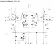
Notice the difference between the values of pin 15 and 5 (pin 5 is half of pin 15). I measured all the resistor/caps connected to these pins and they seem ok. (see the internal schematic of chip) Any ideas as to why this difference might be.
And also what is pin 4? is 14.65V seem about correct?? someone with some experience with the STK4191 or STK4192 can answer this may be...
I measured the voltage at all the pins of the STK:
pin 1 - 0.3V (input R)
pin 2 - 0.34V
pin 3 - 0V (gnd)
pin 4 - -14.65V
pin 5 - -0.7V
pin 6 - NC
pin 7 - NC
pin 8 - NC
pin 9 - -45V (-Vcc)
pin 10 - 29mV (Rch out)
pin 11 - +45V (+Vdd)
pin 12 - +44V
pin 13 - 96mV (Lch out)
pin 14 - -45V (-Vcc)
pin 15 - -1.4V
pin 16 - 0v (gnd)
pin 17 - 0.38V
pin 18 - 0.34V (input L)
Notice the difference between the values of pin 15 and 5 (pin 5 is half of pin 15). I measured all the resistor/caps connected to these pins and they seem ok. (see the internal schematic of chip) Any ideas as to why this difference might be.
And also what is pin 4? is 14.65V seem about correct?? someone with some experience with the STK4191 or STK4192 can answer this may be...
Attachments
Last edited:
- Status
- Not open for further replies.
- Home
- Amplifiers
- Chip Amps
- Pioneer chip amp problem..Arrgh!!!