Thanks Mooly, I'm aware of the glue needed to hold the IC body after placement but I didn't think that would be evident until you had actually removed the solder and freed the IC. I assumed we were not this far advanced yet if the chipquick extraction was still in the planning stage. Hence the puzzlement.
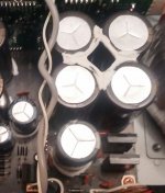
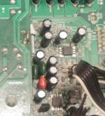
The glue is diagonally placed over the IC and onto the board either side. It is also set on other components throughout the amp - presumably as an antivibration measure.
That's bizarre. It renders those affected areas irreparable if hard glue. Are you the original owner and does this look to be done professionally? Otherwise, I'd conclude that this was an earlier, unwise attempt at eliminating the noises.The glue is diagonally placed over the IC and onto the board either side....
I guess we differ on the understanding of hard glue. That's an elastomer I think, rather like silicone sealant, Its now used generally to prevent larger parts from movement or even tearing out when the unit is dropped or roughly handled. Air and road freight can be cruel to larger electronic assemblies.
I can't see why Pioneer would slap glue over the micro, other than to prevent access to the programming or details - perhaps for compliance with some regulation or other. Anyway, you need to remove as much of it as possible before desoldering and that makes an opportunity to test again before the desoldering.
I don't doubt Pioneer's expertise but I have been caught out by slightly conductive or contaminated glues with MOS circuits in the past. Worth a try I think, for the little extra time involved.
That is a bit odd for sure. I'd agree with Ian having seen that, just pull it off. Conductive glue was a major problem in several brands of TV some years ago causing all manner of inexplicable faults.
Thank you for the tip on the glue. It is much more solid than silicone sealant - I will remove it this evening and retest. Interestingly the tech I spoke to in pioneer suggested that the IC was a rare part, indicating it rarely failed.
When I put a function generator test signal on the input I noticed an audible crackle on volume change. I put a scope on the output and noticed some fairly high transient pulses. I put this down to internal bleed inside the failing IC - could be external through the glue.
When I put a function generator test signal on the input I noticed an audible crackle on volume change. I put a scope on the output and noticed some fairly high transient pulses. I put this down to internal bleed inside the failing IC - could be external through the glue.
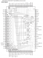
As a general rule in servicing, the large LSI chips are usually the most reliable components in a device... whatever the fault is, its never the big chip. You check and eliminate every possible cause before pointing the finger. That means going around every pin with a scope and seeing if what you expect to see is present, eg the grounds are clean, the supplies are clean... in other words you look at every single pin.
That's not to say that they can't fail however, and of course it doesn't count if the chip has a known and recognised failure mode, which does occasionally happen. Usually in that case, it becomes a well known 'stock fault' within the trade.
That's not to say that they can't fail however, and of course it doesn't count if the chip has a known and recognised failure mode, which does occasionally happen. Usually in that case, it becomes a well known 'stock fault' within the trade.
Cleaned off the white glue. Double checked every pin was clean using a usb microscope and then each connection and solder joint on the board. Played a couple of albums through it in pure clarity and just when I thought it was sorted the popping is back. Worth a go but it looks like i'm back to replacing the IC.
Have you very precisely applied heat and cold to just the chip ? A hot soldering iron tip is actually fine to place on chip itself for a couple of seconds to give it some very rapid heat.
I must admit it does seem to be pointing to the chip though.
I must admit it does seem to be pointing to the chip though.
Thank you for your help with this. So in answer to Moolys questions and a summary.
The popping is volume dependant and appears on left and right channels and the preout.
I have precisely applied focused hot air and freezer spray to the IC and it does have an effect on the popping although it isn't always immediate. Inevitably there will be hot and cold transfer to the area around the IC. Component density in that area of the board is fairly high so I have isolated individual components on the top side of the board eg the opamps, voltage regulators etc and hot and cold or physical shock has no effect on them.
The right channel power transistors are running hotter than the left with no input signal or output load. I can't measure any voltage differences however. Unfortunately I can't disconnect the main amplifiers from the preamp board either via signal or power because the device sees this as a fault and shuts down.
The IC shares the same supply as the Op amps. I have monitored both +/- of this supply on and off load for several hours with a scope. It is stable and clean.
To answer Ians question. The volume control crackle is not audible during normal listening. I applied a 500hz test signal to the input and the crackle is then audible because it is easily distinguished from the steady tone although quiet. The crackle is uniform and apparent when the volume is increased & decreased. Looking at the amplifier output with a scope I can see a very short duration pulse as the volume pot is turned. The volume control is digital and via a separate IC.
In my mind it all points back to the suspect IC or the area beneath it which I can't see until I lift the SMD.
I have sourced a replacement IC from China (this IC carries 100% western feedback) for less than £10. I think at this price it is the next logic step to replace it.

My Chinese £6 (inc delivery) IC turned up during week, taped to a piece of cardboard in a jiffy bag. My hopes weren't high but it was new and identical to the original so I fitted it today. The original IC came off no problem, the pads and circuit traces were all good. The new IC went on surprisingly easily too and it sounds amazing.... as pure & clear as ever....no pops.. no crackles... just music
Thank you everyone for helping - really appreciated 🙂
Thank you everyone for helping - really appreciated 🙂

- Status
- Not open for further replies.
- Home
- Amplifiers
- Solid State
- Pioneer amplifier problem