Hi,
A friend asked me to take a look at a pioneer A401 which is switching off after a few seconds, I checked the output resistor (big white ones) and on one channel the voltage is rising from switch on going up (turned it off when it reached 10v) On the center pin and also the two other pins. I de-soldered the main output transistors and they measure ok in diode mode (so left them disconnected) When these are disconnected the same thing is happening so at least they look ok. The same rising voltage is at the output coil. I disconnected the coil and resistor in parallel.
Voltages at:
Q220 is E=-44.2, C = rishing, B= -43.5
Q232 is E=43.7, C=rishing, B +42.6
=====
Q230
e=rising, c= -45.9, b=rising
Q228
e=rising, c +45.9 , b + rising voltage.
D216 + D220 cathode rising as expected.
D214 + D218 cathode rising as expected, same as collectors from Q220 & Q232
Base of Q224 and Q222 (at R260 & R258 ) same voltage rising at both sides, the center pin (supply on both are ok) , swapped Q222 and Q 224 from the other channel to rule them out, and they are working fine on the other channel.
Q228 & 230Q suspect? R260 and R258 what if I remove one end of these and see which end the Voltage is coming from, is this ok to do?
Any help or suggestions to speed up my slow debug process would be greatly appreciated
Attachments
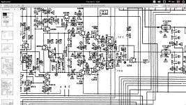
It's a complex DC-coupled amplifier. The fault can be anywhere within the feedback loop. Anywhere.
First of all you should check the feedback network. The thing is never going to work properly if the feedback resistor is open or has a bad joint, or if the capacitor to ground is shorted, or the input ground is not feeling very grounded any more because of a bad joint or open resistor.
Failing that, check the input transistors for any obvious issues.
Hi sgrossklass,
Thanks for your help, yes It looks quite complex circuit alright, just wondering would it be safe to remove (un-solder) the collector from Q220 and Q232 and see is the rising voltage coming from that end, just worried I might fry something else in doing so. I forgot to mention I replaced the electrolytic caps on the failing side and this did not make any difference, the relay clicks on for a while, and then when the voltage rises it shuts down, so the protection circuit is doing what its supposed to. I have inspected the solder connections under magnification already they looked good, but any suspect ones have been re-heated with a tiny bit of new solder with flux. Can you explain a bit more where / what components are part of the feedback loop please?
Thanks for your help, yes It looks quite complex circuit alright, just wondering would it be safe to remove (un-solder) the collector from Q220 and Q232 and see is the rising voltage coming from that end, just worried I might fry something else in doing so. I forgot to mention I replaced the electrolytic caps on the failing side and this did not make any difference, the relay clicks on for a while, and then when the voltage rises it shuts down, so the protection circuit is doing what its supposed to. I have inspected the solder connections under magnification already they looked good, but any suspect ones have been re-heated with a tiny bit of new solder with flux. Can you explain a bit more where / what components are part of the feedback loop please?
Ok these are the readings on the negative rail Q238 (A992)
E= -44.1 , C= -45.4 , B= -44.6
Positive rail
44.1, 45.8 & 45.3
Wondering would de-soldering the collector on q219 and the one above it think Q231 be a good idea, so I can rule out that its not coming from that end? What do you think, will I fry anything in doing that?
E= -44.1 , C= -45.4 , B= -44.6
Positive rail
44.1, 45.8 & 45.3
Wondering would de-soldering the collector on q219 and the one above it think Q231 be a good idea, so I can rule out that its not coming from that end? What do you think, will I fry anything in doing that?
Apart from dc-loops and other things, rising of everything around and after the biascircuit happens when the cascode Q218-Q232 sources more current than Q220 sinks.
Some suspects:
R246 (?) Re of Q220 has an !, so can be changed in value, burned or melted.
Cascode-mirror Q216-Q218 same Re (r246) of Q218.
Not clear in this part of the circuit is the full feedback/dc loop. Can be an instabillity or broken differential input and suggestions above. Can you provide us a larger picture?
Got the ServMan... tb cont.
Last edited:
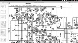
Reading over R212 and R214 (output from diff) should be equal, take ref from minusrail.
If unequal, the input diff is out of balance.
Same reading should be on R228 (Re of Q212). If not, Q204/Q212 broken.
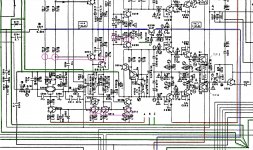
Reading over R222, R234 and R218 (ref to plusrail) should be equal too. If not check readings over C220 and C222. Should be equal to other ch R219 and C221 resp.
Post readings please, some calculations seems not to make sense.
Shorten cathodes D218, D216 to output and other ch D215, D217 to output for static zerobias. Output stage is protected, bias is zero and primary and amp stages are normal.
If output voltage still rises, it's not the endstage.
If unequal, the input diff is out of balance.
Same reading should be on R228 (Re of Q212). If not, Q204/Q212 broken.
Reading over R222, R234 and R218 (ref to plusrail) should be equal too. If not check readings over C220 and C222. Should be equal to other ch R219 and C221 resp.
Post readings please, some calculations seems not to make sense.
Shorten cathodes D218, D216 to output and other ch D215, D217 to output for static zerobias. Output stage is protected, bias is zero and primary and amp stages are normal.
If output voltage still rises, it's not the endstage.
Hi MarsBravo,
Thanks so much for your help, the schmatic is starting to look blurry at this stage. These are my readings as requested.
Near Q202 with reference from the negative rail resistor R213 from first power on starts at 3.4V and goes to 4.05V then it dropped slightly to 4.02V.
Q201 on R214 its stable at 3.16V
Is this enough of a differential to cause this issue?
R222, R234 and R248 (i presume you mean this? its so hard to see) with ref to the positive rail (negative lead on positive rail) I am getting -1.3V and -2V on all resistors.
I will short the diodes as requested tomorrow. Thanks again
I shall look upon it in detail this morning, but sofar the inputdiff is out of balance (both collectors of Q202 should be equal). The outputleg shift from initial 3.40 (compare wih other leg at 3.16) and then raises further, where it should go a bit lower. The diff is trying to correct the output. The 1.3 and 2.0 reading on the posrail indicates (should all be the same) problems arise from the Q204-Q212 combo, the current mirrors Q208-234-218) or something around the C222 RC network.
Hi Mooly,
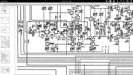
Q238 on the negative rail and Q237 on the positive rail identical setup , I will take voltage readings on all the pins in a few hours on both rails, the supply voltage to the emitters is spot on, I already measured these earlier.
OK.
As the fault seems non destructive I would allow the output to settle at whatever value it rises to and then try and look for points within the loop where the voltages are greatly in error.
For example if the output is at +10 volts then the differential input stage should be trying to turn on Q203 which in turn will turn off Q211 and allow Q217 to be off. In that condition the main output voltage should be pulled toward the negative rail via Q219.
It would be worth carefully measuring all the B-E volt drops across those small signal transistors. All should be in the 600 to 750mv range give or take. The PNP's will have the emitter as the more positive, vice versa for the NPN's.
Hi,
Thanks MarsBravo for the offer of the 401 but unfortunately I live in Ireland, but originally from the Netherlands. I will have to revisit this one again next Monday - Wednesday. He also has an marantz pm40SE in for a service / well initial testing it looks more than just a service. hopefully this will be any easier fix, maybe some bad solder joints or bad electrolytic caps, wishful thinking.") I think he will be happy if I get one of them going anyway. So might crack this one open next week.
I think he will be happy if I get one of them going anyway. So might crack this one open next week.
Mooly yes it seem none destructive luckily, I will take another look and take some more measurements as you suggested, I will get back next week.
Thanks
Thanks MarsBravo for the offer of the 401 but unfortunately I live in Ireland, but originally from the Netherlands. I will have to revisit this one again next Monday - Wednesday. He also has an marantz pm40SE in for a service / well initial testing it looks more than just a service. hopefully this will be any easier fix, maybe some bad solder joints or bad electrolytic caps, wishful thinking.
I think he will be happy if I get one of them going anyway. So might crack this one open next week.Mooly yes it seem none destructive luckily, I will take another look and take some more measurements as you suggested, I will get back next week.
Thanks
- Status
- This old topic is closed. If you want to reopen this topic, contact a moderator using the "Report Post" button.
- Home
- Amplifiers
- Solid State
- pioneer A401 / A400