The zeners can be a slightly higher wattage if needed, but not voltage. Leaving hot running parts high off the board can reduce board temperature but increase the part temperature because the board and its copper traces serve to dissipate the heat.
So I assume moving from 1/2w parts to 1w and leaving them off the board (since there are already burn marks on the PCB, hence my concern) would be no issue?
These look suitable.
BZX85C22 Fairchild Semiconductor | Mouser
There is no parts listing for this amp in the service manual. They just give you a part number on the page with the diagram. These original diodes are RD22EB RD22EB pdf, RD22EB description, RD22EB datasheets, RD22EB view ::: ALLDATASHEET :::
BZX85C22 Fairchild Semiconductor | Mouser
There is no parts listing for this amp in the service manual. They just give you a part number on the page with the diagram. These original diodes are RD22EB RD22EB pdf, RD22EB description, RD22EB datasheets, RD22EB view ::: ALLDATASHEET :::
Anyone know anything about replacing these wire wrap connections with something less expensive to work on? You need special tools to wrap and unwrap them (without destroying the wire...) and they are exorbitantly priced. I smell something proprietary. What can I replace these connections with on an (extremely) small budget without soldering everything and making it extremely difficult to service?
Going from 0.5 to 1 watt is fine for the zeners. PCB's that look burnt aren't always a danger sign. Some board material readily discolours with heat as part of a natural process.
No idea for your wire wraps beyond cutting/removing and soldering. I never liked wire wrap as a construction method although the integrity of the joint is first rate when undisturbed.
No idea for your wire wraps beyond cutting/removing and soldering. I never liked wire wrap as a construction method although the integrity of the joint is first rate when undisturbed.
I fashioned a wire wrap tool from a ballpoint pen tube today. My wraps aren't pretty, but functional. I added a small cap of solder on top of the first turn of each wrap so they will be easy to clean with wick when service is needed.
Last edited:
Thank you for all of the good advice. I'd like to get this amp playing properly, it really isn't a bad unit.
Diodes come tomorrow. Ribbon cable on Thursday. I will report my findings once I install the new diodes and listen. I have also ordered two RCAs to add a direct input, bypassing all tone controls and input selection etc. If someone could help me find a place to send the signal and suggest any other components that should be placed before it I would appreciate it.
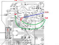
To remove the tone controls from the circuit involves linking the right hand differential amps FET gate to the components to the right of it and removing the connections 18-1 and 18-2
To get a direct input depends whether or not you want to keep the volume control (or just use it as a power amp).
To get a direct input depends whether or not you want to keep the volume control (or just use it as a power amp).
To remove the tone controls from the circuit involves linking the right hand differential amps FET gate to the components to the right of it and removing the connections 18-1 and 18-2
To get a direct input depends whether or not you want to keep the volume control (or just use it as a power amp).
I can lose the volume control, if I implement it I will use it to attenuate the incoming line signal like a passive preamp. I have an outboard passive preamp so it doesn't really matter- but this amp has a nice potentiometer. I assume connections 18-1/2 are pins 1 and 2 of "J18" the six pin plug. I have found the differential fets you mention, is this to be done to the right channel or the right side of the board? If the right side of the board, what side am I looking at and from which direction? What connections should I make?


I'm not sure I follow which pins those would be on the actual board. Could you possibly show me this on the circuit board drawing, not the diagram? The pin labeling appears to differ.
I received the replacement zener diodes and phono jacks today as well. I will replace the diodes even if they are good. They are a known point of failure in this design and they appear to run quite hot judging by the board discoloration. I will be receiving new ribbon cable tomorrow, and will place only the necessary strands to the voltage amp once I understand which pins to ignore properly. Should I make the connection to the fets with a resistor, and what value? Or just use a jumper? Don't want to go on and make a mistake.
I will try this in a manner that will make it reversible, first, and ensure the stability of the circuit. What I am afraid of is harming one of those FET pairs, which are no longer available and routinely sell for $40+ NOS if you can even find them. They also seem to have no equivalent replacement. Have you heard of these? K129A... They seem to give people trouble in older Nakamichi units too.
I will try excluding these wires from the connector and placing a jumper through the existing holes in the PCB. In fact, I will first try a resistor- determine the value by seeing what kind of load the tone controls were presenting. I am sure it is not a dead short, the designers may have accounted for this, or maybe I give them too much credit.
Can't say I've ever come across the 2SK dual FET's tbh (other than seeing them in older gear like this).
It looks like the "line straight" button is doing basically what you are talking about, but there are still two 47k ohm resistors connecting the tone controls when the switch is engaged. Is this anything to be concerned about? Maybe these controls need to be in place? I would just test it but I don't want anything to smoke, particularly those uobtanium FETs.

My other theory is that these resistors serve to eliminate "pop" when you throw the switch and the amp is on by minimizing the difference in potential between these circuits. Would that seem ordinary?
Also, if I were to add a "bypass everything" direct input, would the last two wires in J18 be the place? Or the studs that have the volume pot connected to them labeled "IN" ? I am trying to figure out whether or not just to omit this connection "J18" and leave the center pins floating if they are not necessary.
These connections look like part of the tone controls too. Appears the amp would play if they were omitted since they don't connect to each other anywhere on this board.
EDIT: Ohm meter confirms, these pins may know each other but they don't hang out on the weekends. There is about 35ohms between 1-2, 4-6.

EDIT: Ohm meter confirms, these pins may know each other but they don't hang out on the weekends. There is about 35ohms between 1-2, 4-6.
Last edited:
- Status
- Not open for further replies.
- Home
- Amplifiers
- Solid State
- Pioneer A-77X channel balance