Jaka Racman said:
Hi Elso,
where have you got HC04 from? The photo clearly shows two SOT23 devices together with four thick film resistors, one X7R blocking capacitor and another COG(NPO) coupling capacitor. It seems that the circuit uses grounded emitter output stage. Pretty much standard discrete design.
Best regards,
Jaka Racman
Thanks Jaka !
Elso,
the first canned oszillator did not have TTL output, so I added that 7414.
This is not necessary anymore as the new one has 0 to 3,5V swing.
But I understand that it is good to have a precision comparator after the oszillator, is there a substitute for the one you use in your clock ? And for the fet also ?

Discrete Oscillator
Hi Jaka,
Great. This clearly shows that even that one eye of the cyclops isn' t functioning optimal.
I hope it sounds good.
Jaka Racman said:
Hi Elso,
where have you got HC04 from? The photo clearly shows two SOT23 devices together with four thick film resistors, one X7R blocking capacitor and another COG(NPO) coupling capacitor. It seems that the circuit uses grounded emitter output stage. Pretty much standard discrete design.
Best regards,
Jaka Racman
Hi Jaka,
Great. This clearly shows that even that one eye of the cyclops isn' t functioning optimal.
I hope it sounds good.
FET/ Comparator
Bernard,
Why do you want substitutes for the comparator and the FET?
The parts specified gave the best results.
Bernhard said:
Thanks Jaka !
Elso,
the first canned oszillator did not have TTL output, so I added that 7414.
This is not necessary anymore as the new one has 0 to 3,5V swing.
But I understand that it is good to have a precision comparator after the oszillator, is there a substitute for the one you use in yur clock ? And for the fet also ?
Bernard,
Why do you want substitutes for the comparator and the FET?
The parts specified gave the best results.
Hope your not installing your new clock on the microprocessor pcb (looks that way)😀
Seems to be a 650, do yourself a favoure and rebuild the display powersupply on the filterpcb on some veroboard. You then have lots of space for mods😉
Seems to be one of the older versions. PCB for the microprocessor instead of just the chip and no 7210 (i think) but M4808. Looks familiar😉 allthough i have swapped the microprocessor pcb for the chip (killed the first one).
mvg,
guido said:Hope your not installing your new clock on the microprocessor pcb (looks that way)😀
Seems to be a 650, do yourself a favoure and rebuild the display powersupply on the filterpcb on some veroboard. You then have lots of space for mods😉
Seems to be one of the older versions. PCB for the microprocessor instead of just the chip and no 7210 (i think) but M4808. Looks familiar😉 allthough i have swapped the microprocessor pcb for the chip (killed the first one).
mvg,
Yes, the clock is on the microprozessor PCB 😀
The CD650 is my test victim.
Not for normal listening.
With the M4808 it sounds and measures as good as any CD880 or CD304mkII.
Note the extra PCB for the parallel TDA1541 on the right side 😀
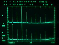
Here comes distortion spectrum ( linear vertical scale )
Comparison between
CD650 non os mode = lower graph.
new clock, unmodded output stage, TDA1541A in parallel board with bad wireing
CD880 non os mode = upper graph.
original SAA clock, modded output stage with opa2604 & MKP everywhere, same (!) TDA chip.
Looks very much the same, just K3 is 3,7dB better and K9 very little better in CD880.
With any other TDA chip it looks very very different !
Attachments
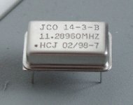
We don't wonder anymore if crystal quality is important, it is. The type you're showing seems a special audiotype. Maybe you can find specs on the web ?
No jitter specs. Nevertheless it'll be better than standard clock circuits.
Don't forget an output series resistor when using one ( 47 Ohm ).
Don't forget an output series resistor when using one ( 47 Ohm ).
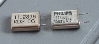
50ppm
The 50 ppm is a frequency deviation spec. Remember 1ppm is 1/1000000. This 50 ppm is AOK in my opinion. Even trained musicians use a tuning fork. Now how accurate is that?
What is far more important is the jitter spec but this is not given on your spec. sheet. And even if it is available it does not say all.
Best try the oscillator(s) you are interested in, in your own CD player. Players of different model and make "react" differently to add-on clocks as I learned.
I have found researching power supplies that a very low noise power supply may yield very low jitter but can produce a totally uninteresting, non-involving sound! Weird!😎
Hi Bernard,Bernhard said:Here it is, it is standard 50ppm.
Any good ?
The 50 ppm is a frequency deviation spec. Remember 1ppm is 1/1000000. This 50 ppm is AOK in my opinion. Even trained musicians use a tuning fork. Now how accurate is that?
What is far more important is the jitter spec but this is not given on your spec. sheet. And even if it is available it does not say all.
Best try the oscillator(s) you are interested in, in your own CD player. Players of different model and make "react" differently to add-on clocks as I learned.
I have found researching power supplies that a very low noise power supply may yield very low jitter but can produce a totally uninteresting, non-involving sound! Weird!😎
Bernard,Bernhard said:Frequency is for 20°C.
If it is warmer like in a CDP it will run too fast.
Not bad, ehh ???
My attempts are fruitless. I give up.

Elso Kwak said:
Bernard,
My attempts are fruitless. I give up.
Huhu, good morning !!!
I will try your clock and I will try this one.
And measure distortion.
By the way, did you measure distortion with and without your clock ?
Could you post something ?
Would be interesting.
Yes, harmonic distortion with different clocks like you see it in the pictures in recent postings.
Why ?
I did some research in the solid state forum and it is clear to me now:
Non os sounds better, more involving, because of relative strong even order harmonic distortion.
Why ?
I did some research in the solid state forum and it is clear to me now:
Non os sounds better, more involving, because of relative strong even order harmonic distortion.
Actually I see it being pretty similar.
How did you find it about strong even order distortion? How much is it strong?
How did you find it about strong even order distortion? How much is it strong?
Pedja,
I have tested about 20 TDAs and it is obvious that in each possible combination of Os / Non OS & TDA1541 / A & SAA7220A / B all TDAs have the similar distortion spectrum.
That means that with OS & 7220A & 1541A all 1541A have very similar spectrum, but still different from chip to chip.
Look @ post#27, non os with 2 different clocks.
Examples:
Non Os with 1541A: Dominating even orders, sounds good.
K2 -50,7 K3 -57,4 K4 -50 K5 -59,9 K6 -51,5 K7 -58,5 K8 -51,3 K9 -64,2
OS with 7220A & 1541: Best objective performance.
K2 -56,8 K3 -59,1 K4 -57,5 K5 -61,7 K6 -57,8 K7 -62,6 K8 -58,2 K9 -58,2
OS with 7220B & 1541A: Dominating K5 & other odd orders little dominating.
K2 -64,8 K3 -56,9 K4 -66,3 K5 - 54,4 K6 -67,9 K7 -66,8 K8 -67,1 K9 -60,4
Non OS with 1541: Very bad, dominating odd orders.
OS with 7220A & 1541A: Very bad, dominating odd orders.
Note:
Values around -67dB might be even better, but I can't see it because -68 is noise floor of DAC + preamp + analyzer with the -60dB 1 kHz CD.
- Status
- Not open for further replies.
- Home
- Source & Line
- Digital Source
- pinout of standard crystal oszillators ?