Hi 🙂
I don't know if this is the right place for this but I'll give it a try...
I have been looking around the web for information on a Phantom Powered Pink Noise generator, but so far the only thing I can find is ready made equipment.
thought I might try to come up with something on "my own" then.
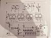
Found a pink noise generator described on http://sound.westhost.com/ , mixed with a phantom power "PSU" found another place, and added a SSM2142 and came up with this (attached) schematic.
What's bother me a little is that the SSM2142 is needing a differential power supply, while the OP-amp doesn't.
I don't think this should be a big problem as long as the parts is ac-coupled, but I might be proven wrong here.
Decided that I should ask You...before I actually build this one...does this look OK to You ?
...or am I way out here ??
The two 0-ohms resistor is there of one reson only...they make the layout a little bit easier to route on a single side board (are using Eagle)
The SSM2142 is chosen over a transformer of one reason only...cost.
The TL072P is chosen because this was the OP-amp chosen in the original P.N.G., and this thing is meant to make noise, so I don't need a high priced Low Noise OP-amp here !
There also might come in handy to have some kind of gain control between the OP-amps and the balanced line driver !?, but this could be implemented very easy a little later.
Regards
Lyra
Sorry, but the format of the drawing made me attach a zip-file...I had problems making it small enough...
I don't know if this is the right place for this but I'll give it a try...
I have been looking around the web for information on a Phantom Powered Pink Noise generator, but so far the only thing I can find is ready made equipment.
thought I might try to come up with something on "my own" then.
Found a pink noise generator described on http://sound.westhost.com/ , mixed with a phantom power "PSU" found another place, and added a SSM2142 and came up with this (attached) schematic.
What's bother me a little is that the SSM2142 is needing a differential power supply, while the OP-amp doesn't.
I don't think this should be a big problem as long as the parts is ac-coupled, but I might be proven wrong here.
Decided that I should ask You...before I actually build this one...does this look OK to You ?
...or am I way out here ??
The two 0-ohms resistor is there of one reson only...they make the layout a little bit easier to route on a single side board (are using Eagle)
The SSM2142 is chosen over a transformer of one reason only...cost.
The TL072P is chosen because this was the OP-amp chosen in the original P.N.G., and this thing is meant to make noise, so I don't need a high priced Low Noise OP-amp here !
There also might come in handy to have some kind of gain control between the OP-amps and the balanced line driver !?, but this could be implemented very easy a little later.
Regards
Lyra
Sorry, but the format of the drawing made me attach a zip-file...I had problems making it small enough...
Attachments
davidsrsb said:Digital approaches are far more predictable and can be cheap these days.
Have tried one of this, and don't like it. There was something strange with the sound it produced. Just like "something" was somehow rumbling back and fourth...coming an going !?
Difficult to explain...😕
...and pink noise generators are easy to come by, but I want a small unit that is powered via phantom power delivered by the audio mixer...and theese are not so common...they do exist, but haven't found any with a reasonable price tag yet.
Lyra
Digital noise generators always have a repetition rate which must be long enough to avoid low frequency artifacts. Once you meet this point, the performance is nearer ideal than most analogue methods. The latter have problems with rising noise levels at low frequencies and bursty shot noise.
davidsrsb:
I Your oppinion...is one of the following sollutions good enough:
http://www.edn.com/contents/images/80703di.pdf
http://www.discovercircuits.com/PDF-FILES/noisegen.pdf
???
Lyra
I Your oppinion...is one of the following sollutions good enough:
http://www.edn.com/contents/images/80703di.pdf
http://www.discovercircuits.com/PDF-FILES/noisegen.pdf
???
Lyra
The second one is 25 stages so, if the tapping is correct, the sequence is (2^25) - 1 or 33.5E6, which is long enough. The output spectrum is white modified with a sinx/x curve, so 25KHz clock is far too low - 100KHz is minimum.
I think that the 4006 is long obsolete.
There is a tool at http://www.eecircle.com/applets/009/LFSR.html for finding the tap points.
I think that the 4006 is long obsolete.
There is a tool at http://www.eecircle.com/applets/009/LFSR.html for finding the tap points.
davidsrsb said:The second one is 25 stages so, if the tapping is correct, the sequence is (2^25) - 1 or 33.5E6, which is long enough. The output spectrum is white modified with a sinx/x curve, so 25KHz clock is far too low - 100KHz is minimum.
I think that the 4006 is long obsolete.
There is a tool at http://www.eecircle.com/applets/009/LFSR.html for finding the tap points.
I'm afraid You lost me there 😕 ....
...but will the old Elektor noise generator (attached) be good enough ?
(thanks to moamps for sharing this...!)
Lyra
Attachments
The Elektor circuit has an even longer sequence so it should be OK. It uses more common devices so it may be easier to build.
I don't know if the pinking filter is correct.
I don't know if the pinking filter is correct.
davidsrsb said:....I don't know if the pinking filter is correct.
It looks loke some kind of older passive filterdesign.
I may be better of if replacing the filter with the one from westhost ?
Think that one at least is decent "pink"...!?
I may also be better off if replacing the "original" SSM2142 with some OP-amps...

Lyra
davidsrsb said:It would not have been an Elektor design without an oddball device like that SSM2142.
???
The SSM2142 is not part of the "original" Elektor design...it is a balanced line driver I've implemented with "my version" of the Westhost design...
Lyra
davidsrsb said:The Elektor circuit has an even longer sequence so it should be OK. It uses more common devices so it may be easier to build.
I don't know if the pinking filter is correct.
Hi:
The sequence is 2^31-1. -3dB/oct filter accuracy is very good and better than that published on the Elliot's site.
Regards,
Milan
moamps said:
Hi:
The sequence is 2^31-1. -3dB/oct filter accuracy is very good and better than that published on the Elliot's site.
Regards,
Milan
Thanks 🙂
This was good news...
Think I'll have to see if I can use this one then...but not this night...
Lyra
- Status
- Not open for further replies.
- Home
- Source & Line
- Analog Line Level
- Pink Noise generator