Hi, I am attempting an upgrade/repair of a KT88 Push pull Chinese Amplifier. I want to convert it to Triode Mode only and convert as much as possible to Hard Wiring.
I have circuit diagram and all details, so theory is in place but I have a practical question which I would like some advice on.
I have decided to bypass the switching circuitry, relay, plus mode switch and wire direct. Can I solder Pin 4 Grid Resistor directly to Pin 3 or should I take the connection directly from HT supply with separate cable. I know it is almost the same electrical connection, but would like to know which is preferable from the good practice point of view.
Thanks
Aug
The former gives triode mode. The latter gives pentode mode. It is a completely different electrical connection; indeed it is the essence of the change you are making!Aug said:Can I solder Pin 4 Grid Resistor directly to Pin 3 or should I take the connection directly from HT supply with separate cable.
Pin 4 Grid Resistor
Hi, thanks for your rapid reply.
I can see I've posed an incorrect question.
I should have said Anode connections rather than HT.
The Amplifier in question was supposed to be switchable between Triode Mode and Ultra Linear, but I found the Amplifier became unstable in one of the modes. On investigation I found that it could not be run in UL as it does not have an UL transformer. It appears some fudging has been carried out so it appears it has 2 modes. From what I can ascertain, all the switch is doing is switching pin 3 to pin 4 via a 100R resistor or switching another 100 resistor in series with the Anode connections to give another mode of operation which I can't quite fathom out. The question I should have asked is, from the point where Transformer connects to PCB/Anodes, Should I attach a wire to that point and tag resistor on to that to pin 4 or just wire resistor from pin 3 to pin 4?
I hope this makes things a little clearer.
Thanks
Just put the resistor from pin 3 to 4.
Why remove the switch if it isn't doing anything? You must be in triode mode already.
Why remove the switch if it isn't doing anything? You must be in triode mode already.
Hi again, can any of you guys she'd any light on the switching of the 270R resistor into the HT circuit? It's a bit confusing but it appears to come off the HT feed, into the switch that would switch from Triode to UL, so appears to just add it's series resistance to the 100R Grid resistors. Only one resistor, which feeds both halves of the PP?
My crystal ball is away for repair at present, so I can't see the circuit diagram in front of you.
Please draw a schematic diagram of the amp's wiring, and submit that here.
An accurate drawing of the wiring to the KT88 would be a huge help.
--
An accurate drawing of the wiring to the KT88 would be a huge help.
--
Hi, Lol, making some unreasonable assumptions from you guys.
I have attempted to attach the circuit to this reply.
Not sure if I've done it successfully, but I'm sure you'll soon let me know.
It obviously does not contain any info about the 270 R resistor, as this was supposed to be an UL Amplifier and from what I can see, this is something they done to simulate the 2 modes.
Please let me know if you can access the attachment, then we can take it from there.
Thanks
Attachments
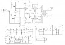
Actually, that's your basic Triode/UL switch. The resistor going to the screen grid could be 270R, that would make sense.
- When the 270R resistor is connected from the KT88 screen grid to the audio output transformer's primary tap, the output stage is wired for ultralinear or distributed load operation.

- When the 270R resistor is connected from the KT88 screen grid to the KT88 plate (anode), the output stage is wired for triode operation.
Does the wiring in the amp agree 100% with the schematic?
--
- When the 270R resistor is connected from the KT88 screen grid to the audio output transformer's primary tap, the output stage is wired for ultralinear or distributed load operation.
- When the 270R resistor is connected from the KT88 screen grid to the KT88 plate (anode), the output stage is wired for triode operation.
Does the wiring in the amp agree 100% with the schematic?
--
Last edited:
Hi, I've had another look at it since I posted, it's a bit confusing for me not being a Tube Expert, but I made some notes while activating the switch/relay. Hope I've got it right, but feel free to ask me any further specifics. In one position, the HT routes via 270 ohms to feed the 2 Grids, in the other position, it switches 100 Ohms between Anode and Grid. This is where I'm confused. As I think you are saying in your reply, the Triode connection should be the position where the 100 Ohms is connected between anode and grid, but what is it doing in the other position? As I mentioned before, it can't work in Ultra Linear as it does not have an UL Transformer. Only 3 Primary Connections. CT and the 2 Anode feeds?
There's some confusion going on. The KT88 has two grids. Each one has a control grid (pin 5) and a screen grid (pin 4).
If you connect a 270 ohm resistor between the anode (pin 3) and control grid (pin 5), bad things would happen.
Are you saying the control grid and screen grid are connected together (shorted)? That would not be a good thing, normally.
Is that a different resistor? I thought it was a 270 ohm resistor. This is confusing.
Obviously, the schematic you posted is not the same as the amp you have. Please post a schematic that shows the actual wiring in your amp.
--
If you connect a 270 ohm resistor between the anode (pin 3) and control grid (pin 5), bad things would happen.
In one position, the HT routes via 270 ohms to feed the 2 Grids,
Are you saying the control grid and screen grid are connected together (shorted)? That would not be a good thing, normally.
in the other position, it switches 100 Ohms between Anode and Grid.
Is that a different resistor? I thought it was a 270 ohm resistor. This is confusing.
it can't work in Ultra Linear as it does not have an UL Transformer. Only 3 Primary Connections. CT and the 2 Anode feeds?
Obviously, the schematic you posted is not the same as the amp you have. Please post a schematic that shows the actual wiring in your amp.
--
No, none of the switching is connected to pin 5, this is all centred around pin 4. There is only 1 270R resistors, but 2 100R.
The circuit I believe would have been correct for the amp if as I think, they didn't decide to cut corners and not fit an UL Transformer. The 270 Ohm resistor doesn't appear on the Diagram and there is no screen ident for it. That's why I think it was added as something that would work as an alternative to Triode Mode, a Sort of Dummy Pseudo UL.
The circuit I believe would have been correct for the amp if as I think, they didn't decide to cut corners and not fit an UL Transformer. The 270 Ohm resistor doesn't appear on the Diagram and there is no screen ident for it. That's why I think it was added as something that would work as an alternative to Triode Mode, a Sort of Dummy Pseudo UL.
My crystal ball's not working either. Please post a schematic that shows exactly how that amp is wired.
I'm going to attempt to draw out wiring tomorrow, but I think part of the confusion has been my mention of the 270 Ohms feeding 2 Grids. What I meant is the single and only 270 Ohm resistor feeds both O/P valve Grids, pin 4.
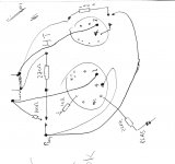
Difficult to make much sense of that, but I suspect the amp you have is switchable between triode and pentode mode - with a common g2 resistor for pentode.
- Status
- Not open for further replies.
- Home
- Amplifiers
- Tubes / Valves
- Pin 4 Grid 2 Resistor