Before we get started: I have started down the correct path of crossovers and HF drivers and I HAVE NO INTENTION OF DOING THIS!
so any answers saying that you shouldn't do it are - well dumb, BUT since I was thinking about it and couldn't find the answer I'm going to ask about the science anyway.
Assuming a high power system incorporating at least one conventional LF driver in parallel, how would you add piezo(s) in such a way that they wouldn't blow? I know that you should add a cap to raise the frequency but there is still a lot of energy to absorb. You might need more than one to balance the system.
So; Technically; how should it be done?
A series resistor and a suitably rated MOV. You'd have to know the max amplitude of the signal that the piezo can handle - and the signal amplitude that will crack it. Choose the MOV voltage somewhere in between - if they even make such a thing; most are rated at AC power line voltage levels.
What this will do is clip the signal when it reaches the ampltude that threatens the piezo crystal. Since MOV becomes low Z at that voltage, input signal drops across the resistor. Which would have to be sized relative to the impedance of the piezo array. I imagine some counting number of Ohms...
What this will do is clip the signal when it reaches the ampltude that threatens the piezo crystal. Since MOV becomes low Z at that voltage, input signal drops across the resistor. Which would have to be sized relative to the impedance of the piezo array. I imagine some counting number of Ohms...
Metal Oxide Varistor ??? Yikes! ...did we not have formal schooling on this, or did this "hobby" come to you thru osmosis, a passing interest or???
Some of us have gone thru lots of schooling along these lines, some not...some have had, or still have highly technical careers as such.
We need to know 'how far' we can describe things without yourself giving us all, a blank stare, deer in the headlights posture.
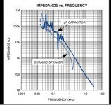
You do know a piezo element functions in a capacitive manner, right?
-----------------------------------------------------------------------Rick...
Some of us have gone thru lots of schooling along these lines, some not...some have had, or still have highly technical careers as such.
We need to know 'how far' we can describe things without yourself giving us all, a blank stare, deer in the headlights posture.
You do know a piezo element functions in a capacitive manner, right?
-----------------------------------------------------------------------Rick...
This PDF could give you the information that you have no intention of usingBefore we get started: I have started down the correct path of crossovers and HF drivers and I HAVE NO INTENTION OF DOING THIS!
So; Technically; how should it be done?

https://www.grc.com/acoustics/CTS_Piezo_Tweeter_AppNote.pdf
We need to clarify here that piezo drivers are attenuated passively with capacitors, not resistors as the load presented to the amplifier is mostly capacitive in nature. The Motorola Powerline series piezo drivers had small bulbs in them for protection. You have to make sure the current is scaled down far enough as the drive currents are smaller and your mostly dealing with frequency dependant loading that presents a falling impedance curve without the VC DC resistance of a standard comp driver.
Attachments
That CTS app note has all you need to know and then some but anyway my own "practical" rule has been to consider them 35V RMS max. devices, so no special attenuation neded in my popular 300W into 4 ohm power amp modules (Bass - PA - Keyboard) which they match like a glove.
Nothing beyond a 47 ohm 1 W series resistor per tweeter, or equivalent needed, and that more to avoid unnecessary capacitive loads on my amps than "tweeter protection" per se.
That said, sometimes a customer complains of "dead tweeters" in a cabinet, when open they show burnt on series resistors.
When I see that, I immediately inspect related power amps and usually find toasted Zobel resistors, same thing, both caused by amp oscillation.
IF you have a higher than 35V RMS out amp, yes, a 50V MOV across the tweeter terminals provides protection.
Think of it as of a "robust Zener"
There are Tweeter protection circuits based on a bridge rectifier, a power transistor and a Collector to Base Zener to mimic a very high power Zener, very safe but fell out of favour because they clip HORRIBLE, adding an unbearable buzz sound.
Have yet to compare this tutorial to the CTS doc, so for now posted for subject ~completeness:
Posted By: Jon Risch <jrisch@strato.net>
Date: 6/2/99 22:15
= The Parts Express catalog suggests putting a
= 22-Ohm resister inline w/ any Piezo tweeter
= to make it a more stable load for an amp.
= Will this not also attenuate the tweeter? If
= so, and if I need further attenuation, can I
= simply add more resistance? Is there a rule
= of thumb for how much attenuation I will get
= with further resistance, or a way to compute
= this number?
The recommended resistor is to help protect the amplifier from the raw
capacitance that is a piezo driver. Adding resistance in series with a
piezo will actually roll-off the highs a bit, adding more will roll-off the
highs noticeably.
To attenuate a piezo, add a series cap, which creates a voltage divider
with the cap that is the piezo drive element. Most piezo elements run in
the 0.1 to 0.26 uF range, so a cap the same value as the piezo element will
attenuate it 6 dB.
Piezo's can be crossed over, and to great advantage. I have often thought
that some of the bad rap piezo drivers have is due to the "you can use them
without a crossover". Yes, you _can_ use them without a crossover, but
just because you can get away with it, does not mean it is optimal.
Since most piezo's are used in inexpensive systems, the cost of adding in
"unnecessary" components is often never even considered.
How to crossover a piezo:
PE is basically right, add a resistor in parallel, and the driver can be
made to look like a current driven device to any outside components, such
as a crossover cap. However, to keep costs and power dissipation down, an 8
ohm is way too small, the impedance of most piezo's is still quite high at
20 khz, so use a 22 ohm resistor, this makes any series crossover cap
smaller and less expensive, and the resistor dissipates less energy. Use of
an 8 ohm parallel resistor will tend to lose a bit of level too.
For most piezos, use of a 22 ohm resistor, and a 4-4.7 uF cap will allow
the response to be identical to what it was in stock form, but rolls off
the lows at 6 dB/oct below 1 kHz or so. This actually increases the power
handling of the piezo, as it is voltage limited. Exceed the voltage used to
pole (polarize the piezo element during manufacture) the unit, and it will
loose sensitivity, and eventually burn out. Most pro grade piezos will
handle 35 volt transients, and 28 volts continuous, which are 150 watts and
100 watts into 8 ohms respectively.
Add in the cap and 22 ohm resistor, and the power handling could
effectively be quadrupled, as the LF voltages are not imposed upon the
unit, just the HF voltages.
Piezo's crossed over in this manner don't sound as harsh and hashy, and
tend to be quite a bit more reliable.
Many of the piezo units have a mild peak just before they roll off in the
LF, so making the series cap a little smaller can actually flatten response,
and provide even more protection and smoother sound.
For the smaller piezo units that cut off at 4-5 kHz, a series cap of 1.5 uF
will do the trick, larger units that go down to 3 kHz can use a 2.2 uF, and
the large compression driver units meant to be mounted on a horn need about
5 uF, as they do not peak, and any higher would lose the sloping output
even more.
Attenuation, HF roll-off AND the crossing over can all be done at the same
time.
To attenuate, place a cap in between the piezo and the 22 ohm resistor that
is shunting across the unit, then if HF roll-off is desired, use a series R
in this location too. Then the series crossover cap should be in front of
the 22 ohm shunt.
Looking from the amp, first the series crossover cap, say 4 uF, then the 22
ohm shunt from hot to ground, then a series cap of about 0.15 uF for 6 dB
attenuation, and then a series resistor of about 30-50 ohms to tame the
very top end, then the piezo itself.

...Have yet to compare this tutorial to the CTS doc, so for now posted for subject ~completeness:
Excellent post GM that saved me having to write all that out!
A good piezo driver with crossover is an excellent and robust tweeter. I used them crossed like this a nightclub system in the '80s for practically hifi sound. I even did a presentation to the local Audio Engineering Society section on the engineering of the system.
In those days decent musical limiters were expensive and the club wouldn't front up the money for one. When an amplifier is driven into serious clipping it's possible to exceed the safe 28 volt rating of the piezo even from a modest amplifier, so as additional protection I used Electro-Voice STR tweeter protectors modified to trip at ~25Vac. The 'chattering' of the high frequencies on severe clipping was a useful signal to the DJs to turn it down!
Electro-Voice STR Tweeter Protector
Last edited:


Why use piezo , is a budget in play.. a cheap horn driver with a 2inch coil will go louder than a than 10 psyzos

I built and used a couple systems with the original Motorola piezos in the '80's and also had the unfortunate luck to have heard many of these piezo loaded Klipsch cabs(harsh), so this comes from the school of hard knocks. In all cases these systems were used in PA applications where the deficiencies of a particular design tend to be exposed.
Piezos always were a budget driver, with the proper load matching circuit and a crossover they work OK but it's really not hard or expensive to do much better. The biggest limitation of piezos are thier limited dynamic range, they only operate linearly over a very small low voltage range, beyond that they saturate and start producing the frying bacon hash they were notorious for, and if you keep pushing even harder they eventually let out the magic smoke. I have some Motorola diaphrams with holes burnt in them where the crystal element disintegrated. To get around this the common practice was to use lots of them, those curved 6-12unit tweeter boxes were popular for a while but IMO the acoustic results weren't any better. A single decent quality compression driver is miles ahead in overall sound quality.
Piezos always were a budget driver, with the proper load matching circuit and a crossover they work OK but it's really not hard or expensive to do much better. The biggest limitation of piezos are thier limited dynamic range, they only operate linearly over a very small low voltage range, beyond that they saturate and start producing the frying bacon hash they were notorious for, and if you keep pushing even harder they eventually let out the magic smoke. I have some Motorola diaphrams with holes burnt in them where the crystal element disintegrated. To get around this the common practice was to use lots of them, those curved 6-12unit tweeter boxes were popular for a while but IMO the acoustic results weren't any better. A single decent quality compression driver is miles ahead in overall sound quality.
Piezo can sound better than compression driver if done right.
Ducks for cover...
LOL... you better!
If you're talking about supertweeter duty you may have some ground to stand on, but below that you're smoking your lunch.
consistency-wise - I think today's piezo may be consistently worse than the days of Motorola.
BFM takes lots of piezo, chops and "meldes" them.
Did Klipsch do anything to attenuate the bump on the bottom?
I've only seen pictures of 5 1016 in a Klipsch mini-array - but remember the awful horizontal arrays of the 70's and also sounds of "quack" from horns being driven too loud.
(GRS may not be this "smooth")
here's how the late DJK would do it paralleled KSN1016 (or KSN1005)
Excellent.
- Home
- Loudspeakers
- Multi-Way
- Piezos in a high power system - How?