Hello All,
I'm starting a project which involves using a piezo pick up on an acoustic cello. i have a few questions, and any advice or guidance is appreciated!
First off, I was planning on using this as the sensor/pickup:
LDT0-028K/L Measurement Specialties, Inc. | Mouser
am i looking at the correct component for this? any feedback on this component?
Second, i was planning on following these plans for the pre-amp:
http://www.scotthelmke.com/Mint-box-buffer.html
these plans call for a 2N5457 FET, which appears to be obsolete (according to Mouser anyway).
i was thinking about using this instead:
2N5486 Central Semiconductor | Mouser
would i need to manipulate resistor values with this FET swap?
anyway, just looking for advice or suggestions on the pick up as well as the pre-amp before i start this project...i'm kind of just learning to build this stuff - so i'm still a little unsure.
thanks for any help!
That sensor looks cool and the price is definitely right, but what most everybody uses (unless it's the "toothpick sensor" used under the saddle) is just a piezo alarm or buzzer disk, preferrably with both contcts on the same face so the other can be glued or pressed flat against the instrument:


not this:

The preamp is fine, it's not actually that but a simple unity gain buffer, lose the "gain" control, just go straight without it, and I'd lower the Fet Source resistor to something like 47k or even 33k .
Almost any N channel FET will work there, the circuit is so simple, just be aware of FET pinout (check the datasheet) in case they are not the same.
not this:
The preamp is fine, it's not actually that but a simple unity gain buffer, lose the "gain" control, just go straight without it, and I'd lower the Fet Source resistor to something like 47k or even 33k .
Almost any N channel FET will work there, the circuit is so simple, just be aware of FET pinout (check the datasheet) in case they are not the same.
thanks for the reply!
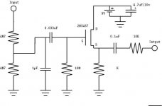
in the original schematic:
"The connection between the two 4M7 resistors is the low-gain setting."
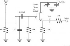
i attached a new schematic according to your suggestions, did i draw it correctly?
and as far as the JFETs, i found this from a different build:
"The JFETs could be just about anything with Idss of 1 to 5mA and cutoff voltage of 1 to 3V"
PZP-1 Piezo Buffer – Technical Info | Cafe Walter Audio
do i need to abide by the above drain and cutoff values for my "mint box buffer" ?
is there a JFET you would suggest from here:
JFET | Mouser
thanks!
in the original schematic:
"The connection between the two 4M7 resistors is the low-gain setting."
i attached a new schematic according to your suggestions, did i draw it correctly?
and as far as the JFETs, i found this from a different build:
"The JFETs could be just about anything with Idss of 1 to 5mA and cutoff voltage of 1 to 3V"
PZP-1 Piezo Buffer – Technical Info | Cafe Walter Audio
do i need to abide by the above drain and cutoff values for my "mint box buffer" ?
is there a JFET you would suggest from here:
JFET | Mouser
thanks!
Attachments
Piezo has gone mainstream in a very big way. On eBay search:
piezo pickup
Select anything, then scroll down to "You may like." Allow some time.
piezo pickup
Select anything, then scroll down to "You may like." Allow some time.
Much better.
* Lose the upper 4M7, go straight into th lower one.
* use 22k or 47k for "K"
* increase the 0.1uF output cap to 1uF
* you may leave the 10k output resistor or lower it to, say, 1k, to drive longer cables.
As of the FET, put a socket there and plug a few (you must always buy a few even if you need just one, they vary WAY too much as a rule) , leave there the one which gives you a source voltage between 2 (or 2.5) V and , say, 4V .
The written specs are fine, and what a manufacturer would pre-order so all he buys in bulk work, but you can buy 5 or 10 and "measure them in the circuit itself" .
There is a test circuit going around, I published one myself ... but your preamp is simple and doubles as a FET tester, go figure 😉
hey! thanks for the reminder about sockets...i can just get this and cut it into 3 in a row, right?:
816-AG11D-ESL TE Connectivity / AMP | Mouser
i attached a new schematic, how does it look? any other suggestions?
thanks a lot for the help and guidance. it's very appreciated.
816-AG11D-ESL TE Connectivity / AMP | Mouser
i attached a new schematic, how does it look? any other suggestions?
thanks a lot for the help and guidance. it's very appreciated.
Attachments
...sockets...i can just get this and cut it into 3 in a row, right?
Probably yes, but below is suggested something that might be a lot more convenient, and the cost including shipping is a wash.
This forum seems to not honor eBay links, so search these for specific items:
40 Pin SIP Socket (1 PC) Breakable Transistor Socket, High Quality. USA Seller
Transistor Sockets/ Female Header 2.54mm spacing. Track comes with 40 x 3
Of course on eBay you always scroll down to "People were also interested in." Or generally search for:
3 pin transistor socket
Just to mention it, eBay has 2N5457s out the wazoo.
.
Last edited:
so, i finally got around to boarding out this project. a few questions/issues...
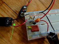
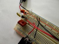
1. for the input jack, how do i hook up the "ring" on the jack? (see photo 01) on the output jack i connected the ring & sleeve together, and then to ground. do i do the same with the input? both of the jacks are "stereo", should i just have gotten "mono" jacks?
2. when i hooked this up to test it, the 4uf capacitor immediately started smoking and burnt up (see photo 02). any ideas why? these should all be non-polorized, right?
thanks for your help with this...i'm still learning and figuring things out!
Attachments
- Status
- Not open for further replies.
- Home
- Live Sound
- Instruments and Amps
- Piezo Pick Up and Pre Amp Project...