Q: I guess it's not as simple as adding a resistor to the feedback loop to increase gain?
adding a feedback network gives you the same schematic as you have now with the opa.........
adding a feedback network gives you the same schematic as you have now with the opa.........
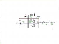
made a sim (without c5=22p):
with R8 = 330k the freq. response is flat up to 100kHz (-3dB around 360kHz).....
with R8 = 330k the freq. response is flat up to 100kHz (-3dB around 360kHz).....
sound more transparent:
you can paralell a plastic cap to the electrolytics (c6,c7).........100nF or so.
perhaps this can help a little bit.........
you can paralell a plastic cap to the electrolytics (c6,c7).........100nF or so.
perhaps this can help a little bit.........
trying to learn more about why the processed sound is not as transparent as I would like it.
The problem here is using meaningless words like 'transparent', which is neither an electronics term nor an audio one, and has no meaning at all. Plotting the frequency response would show you what it's doing, and see how flat it is.
"transparent" meaning a flat frequency response. Meaning the same balance of frequencies that goes into to opAmp circuit comes out the other side, the only difference being a greater amplitude.
The circuit is currently altering with the frequency balance somehow. I mean, with a buffer circuit, yes, the balance SHOULD be altered, but with a gain/circuit, where its primary function is adding gain, the frequency balance should NOT be altered at all.... but currently, with this circuit, it is... at least apparently... as I am trying to figure out if my testing conditions are skewing the results, which I am beginning to think is the case.
I think maybe the problem is.... in recording different conditions, I am not taking into account input impedance mismatches. For example, say I record the following 4 conditions:
1- piezo alone (with sound card gain at max, which adds a lot of noise)
2- piezo plus buffer circuit (with sound card gain at max, which adds a lot of noise)
3- piezo plus opAmp circuit (with sound card gain at min)
4- piezo plus buffer plus opAmp circuit (with sound card gain at min)
then I listen to the frequency balance of each, relative to each other. My assumption (which I am suspecting is wrong now) was that condition 1 and 3 should have the same frequency balance, the only difference being an increase in amplitude. But In this case, would there not be a potential impedance mismatch? For condition 3 (opAmp circuit WITHOUT buffer circuit), if I made the input impedance into the opAmp circuit something like 5M, would that keep the frequency response flat?
Additionally, I've recently thought of one other factor that might be skewing the results. I'm actually using 3 of these piezo sensors wired in parallel, so I definitely shouldn't treat the situation as if I'm only using a single one. This may or may not be significant, I'm not sure. I'm using three sensors spaced out under the guitar bridge to cover all six strings (so one sensor per two strings).
My assumption (which I am suspecting is wrong now) was that condition 1 and 3 should have the same frequency balance, the only difference being an increase in amplitude. But In this case, would there not be a potential impedance mismatch? For condition 3 (opAmp circuit WITHOUT buffer circuit), if I made the input impedance into the opAmp circuit something like 5M, would that keep the frequency response flat?
The buffer is there to give a high input impedance, you can't go directly in the opamp (and if you could, no need for the buffer).
The result will be a massive loss of bass.
There is an alternate method of dealing with piezo's. Using a charge amplifier as the first stage, not a voltage buffer. There are advantages such as very high input resistance, which won't kill high frequency, reduced problems with voltage based noise, and amplifying charge first to bring up signal to a good working level. Then you can apply whatever voltage amplification or filtering you need.
Charge amps are used in instrumentation with piezo type accelerometers and you would have no problem getting in to tens of thousands Hz with no rolloff based on my experience.
For a more ''musical'' application here is some info
Electric violin
Note that you do need an opamp with fet input in order to keep input impedance very high.
Hope this helps.
thanks for all the recent info, definitely VERY useful. Thanks for the info about the "charge amplifier" application shanx, I will also definitely look into this more... looks like the OPA2134 would work nicely for this application as well
one thing I am wondering about from the OPA2134 datasheet:
"SOURCE IMPEDANCE AND DISTORTION For lowest distortion with a source or feedback network which has an impedance greater than 2kΩ, the impedance seen by the positive and negative inputs in noninverting applications should be matched."
was this the issue I was having before?... I mean, was this at least a main reason the frequency balance was altered in the last schematic/circuit I posted, were the two input impedances mismatched?
Last edited:
Hello Lid55,
Looking back on your first post I noted you have three piezo films in parallel.
So, just a couple of points which I think need to be addressed.
In parallel the effective source capacitance has tripled (that may be obvious) and that would mean considerably more high end roll-off for a given buffer circuit, compared to a single film. I did not download the data sheet, but you could measure the capacitance for one film? Then look at the buffer input capacitance.
Are you trying to get a blend of different sounds from different points of the guitar?
If so, would it be preferable to pre-buffer each piezo and then mix/balance the elements rather than parallel them all at source?
Hi shanx, thanks for the reply. The piezo film sensors have a source capacitance of 480pF... so, if i understand it correctly, combined they are 1.42 nF. Would this significantly affect the high frequencies (up to 20kHz)?
I've also found out the right datasheet link... the first one I posted was actually a different model, but looked identical and has identical dimensions, etc. The right PDF datasheet can be found here:
http://www.meas-spec.com/product/t_product.aspx?id=2484
(just a note: to download the datasheet, you DON'T have to register... it just seems that way because they bring up the form... but there's an option to continue without registering)
Last edited:
Hi shanx, thanks for the reply. The piezo film sensors have a source capacitance of 480pF... so, if i understand it correctly, combined they are 1.42 nF. Would this significantly affect the high frequencies (up to 20kHz)?
Connect just one and see how that sounds.
Hi Lid55,
I am estimating the total effective capacitance would be about that, 1.2nF.
Yes this could diminish high frequencies depending on the buffer's input capacitance, the best test of that is to simply try with just 1 transducer and compare with a given buffer.
Regards
I am estimating the total effective capacitance would be about that, 1.2nF.
Yes this could diminish high frequencies depending on the buffer's input capacitance, the best test of that is to simply try with just 1 transducer and compare with a given buffer.
Regards
Thanks for the info. I'm currently looking into testing the single piezo film compared to 3 in parallel, but it'll be a little longer before I can test it out as I have to buy some new parts.
In regards to the main circuit I've been working on in the majority of this forum post, turns out I was definitely testing wrong... and so my results were misleading. Anyways, after increasing the input impedance of the buffer circuit to 10M, and after continued listening tests, what is here so far actually sounds pretty damn good, so thanks for all the help.
On the point of optimizing the the circuit, is there any reason why I can't use a single 10M resistor in place of the first two 20M resistors in parallel in the buffer circuit? I can post a schematic if what I'm talking about here is unclear.
On the point of optimizing the the circuit, is there any reason why I can't use a single 10M resistor in place of the first two 20M resistors in parallel in the buffer circuit? I can post a schematic if what I'm talking about here is unclear.
Post a schematic, but I don't quite see why you would have two 20M anyway?.
Well here is the original buffer circuit... with a gain switch at the beginning. But since I've done away with the gain switch and the 20pF capacitor... I end up with two resistors to ground, one on either side of the input capacitor. Does it matter which side of the capacitor the resistor(s) connect to ground?
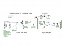
And here's the schematic of my current combo circuit. So in other words, can I combine R1 and R2 to simplify the circuit?
On another note, I AM still wondering about C1 and C3 and C5, the audio coupling capacitors... how these particular values were chosen. I read somewhere in my research (from the BeavisAudio website) that the values of 0.1uF to 1uF is where the full audio frequency range will pass... is this always true... or does it depend on other factors?
Attachments
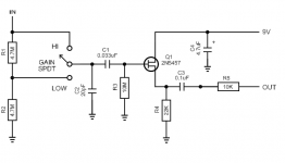
Well here is the original buffer circuit... with a gain switch at the beginning. But since I've done away with the gain switch and the 20pF capacitor... I end up with two resistors to ground, one on either side of the input capacitor. Does it matter which side of the capacitor the resistor(s) connect to ground?
And here's the schematic of my current combo circuit. So in other words, can I combine R1 and R2 to simplify the circuit?
R1 and R2 aren't needed, but you MUST have the gate resistor R3 in place.
R1/2 are just there to implement the gain switch (which seemed pretty bizarre in the first place).
On another note, I AM still wondering about C1 and C3 and C5, the audio coupling capacitors... how these particular values were chosen. I read somewhere in my research (from the BeavisAudio website) that the values of 0.1uF to 1uF is where the full audio frequency range will pass... is this always true... or does it depend on other factors?
Coupling capacitors 'can' be calculated to give the required -3dB point, in conjunction with the load and impedances. But as I've repeatedly said, it's NOT a good idea to try and restrict low frequencies in that way. Generally you would 'calculate' then to give a far lower bass response than you require, or more likely not even 'calculate' them at all - just 'chuck' a suitably large value in there - which is why you see a LOT of 0.1uF's used in high impedance circuits 😀
Q: On another note, I AM still wondering about C1 and C3 and C5, the audio coupling capacitors... how these particular values were chosen.
.......the designer has chosen these values.if you design a schematic,you can choose it (calculate it) for yourself.
i think, the "full audio freq. r. will pass..." means that deep tones go through without attenuation/cut off.
.......the designer has chosen these values.if you design a schematic,you can choose it (calculate it) for yourself.
i think, the "full audio freq. r. will pass..." means that deep tones go through without attenuation/cut off.
- Status
- Not open for further replies.
- Home
- Live Sound
- Instruments and Amps
- Piezo Film Buffer and Amp Combo for Guitar Electronics