Hi,
First of Hi, and a total noob in need of help.
My current PCB design has been setup with input via consumer line-in inputs to a TPA6132A2 for testing and works well (no noise) (I do use a isolated power supply).
I would like to now replace the line-in with 2 preamp circuits for 2x Piezo sensors (automotive).
Specs :-
Range of frequency 3 to 25 kHz
Sensitivity at 5 kHz 26 ± 8 mV/g
Max. sensitivity changing (lifetime)
-17 %
Linearity between 5 to 15 kHz
(from 5 kHz value)
-10 to 10 %
Linearity between 15 to 20 kHz
(linear increasing with freq)
20 to 50 %
Main resonance frequency 30 kHz
Impedance > 1 MOhm
Capacity field 1,150 ± 200 pF
I have seen multiple applications for Piezo guitar pickup preamps though i am limited to a 5V supply.
Can any one help in a circuit or IC to preamp 2 signals enough for the TPA6132A2 or similar headphone IC??
Many thanks
Last edited by a moderator:
What is the expected range of g forces?
How do you expect to wire up the sensors - I assume balanced twisted pair wiring would make sense?
Why are you using a headphone amp IC in the first place?
Any constraints on power supply current usage?
This application is similar to both guitar amplifier and condenser microphone preamp applications. Extrapolating from the latter, you want an input impedance of 15-30 Megohms for best noise levels. (Contrary to intuition, you want input impedance as high as possible when faced with capacitive sources. Condenser mic capsules with something like 30-40 pF a pop are often followed by amplifiers with 10 gigaohm input bias resistors.)
Hence what I would do is a balanced receiver or instrumentation amplifier buffered by a pair of lowish-noise (maybe 10-ish nV/√(Hz)?) FET input (e.g. CMOS) RRIO opamps, e.g. AD8656. (You may have to go with a discrete circuit if you can't find an INA that delivers low enough noise at the kind of presumably rather low gain you need. Get ready for hand-matching 1% or better metal film / thin-film resistors.) I think you could even make an INA with all AD8656s.
Vcc/2 input bias is easily generated by one 100k/(100k+10µF (elect or tant)) between Vcc and GND, from which you could branch off via 10 Megohms to all 4 input legs (if you can't get 10meg resistors, a few 3meg or so parts in series are a safer bet anyway).
Given the high input impedance, it goes without saying that a pair of (normally reverse-biased) Schottky clamping diodes to supply and ground would be a good idea (preceded by a few hundred ohms series resistance in each input leg to limit inrush current), that board contamination is not to be taken lightly, and that other high-impedance design techniques (e.g. guard rings) may be warranted.
Given a >1 nF of the transducer, you can afford a bit of input capacitance without undue loss of signal. I might go with a T-type configuration, with maybe 100p + 100p both going to a 33p to ground. That's 50 pF differential and 28 pF common mode.
Thanks for the reply.
The sensors are for frequency measurement on Vehicle transmissions during testing (solenoid activation, clutch engagement etc).
We use shielded Co-axial cable from the sensors terminating at 3.5 gold mono jack to eliminate ground noise or contamination of signal.
The sensor signal is currently fed to an IC ( which applies biasing to the signal) and the frequency/magnatude etc is then processed.
We want to be able to Monitor the sesnor signals audibly (headphones) through the sensors as well (they basically act as piezo Mics)
Thanks
Last edited by a moderator:
Why not BNC? Much more reliable - 3.5mm jacks are not great, though gold plating is very wise, but they are not designed for a high-vibration environment.Thanks for the reply.
The sensors are for frequency measurement on Vehicle transmissions during testing (solenoid activation, clutch engagement etc).
We use shielded Co-axial cable from the sensors terminating at 3.5 gold mono jack to eliminate ground noise or contamination of signal.
Which IC? Is there any DC-blocking cap or load resistance? Do you have schematic?The sensor signal is currently fed to an IC ( which applies biasing to the signal) and the frequency/magnatude etc is then processed.
We want to be able to Monitor the sesnor signals audibly (headphones) through the sensors as well (they basically act as piezo Mics)
Thanks
We use a common automotive IC used for engine knock detection called the TPIC8101 (see attached Schematic).
Gain is programmable but we can also adjust via R1/R2.
Point noted on using BNC connectors and definately something I will incorporate in new design.
Gain is programmable but we can also adjust via R1/R2.
Point noted on using BNC connectors and definately something I will incorporate in new design.
Attachments
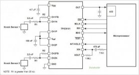
R1 is the load resistor. The signal can be upto 5V p2p at that point depending on the value of the load resistor - piezo's are current sources so the resistor sets the gain as it converts current to voltage.
What values of R1 and R2 are you using?
It may be that you only need attenuation and current buffering.
What values of R1 and R2 are you using?
It may be that you only need attenuation and current buffering.
they are 500k/500k - though the IC circuit and detection works perfectly fine on our system. We would just like to split the piezo output from sensor to another circuit so we can amplify to consumer line levels.
thanks
thanks
At that high impedance you first want an opamp unity-gain buffer, then a volume pot into a headphone amp chip I think.
For a floating source like a piezo transducer, decent coax is probably as good as anything in this application.
If you are going to include a (FET input) unity gain buffer, I would suggest splitting the signal after that. Knock sensor input impedance at the IC is = R1, i.e. 500k, and as outlined earlier you want something well in the Megohms for best performance.
This whole splitting business could turn out to be fun - good luck avoiding ground loops. Better make a plan of all ground connections involved. Strategically placed ground loop breaking resistors may have to be employed.
(Unbalanced signals in a noisy common ground environment like a car are pure hell. In a car audio power amp you may well end up finding balanced input circuitry lurking behind the RCA inputs.)
Last edited:
- Home
- Source & Line
- Analog Line Level
- Piezo device preamp to digital headphone IC (TPA6132A2)