Hello,
I've been disecting an old tube amp of unknown origin or manufacture. Looks like it's from a console or organ. The power supply is unremarkable; classic voltage doubler (SS diodes) followed by a 4-section RC pi filter network.
The fun was tracing the circuit path as there are no tube markings whatsoever. The odd pin-outs were a bit puzzling at first, but they eventually helped identify the tubes that were intended by the designer.
Mostly the topology is straight forward; pentode gain stage followed by a split-load phase splitter driving a cathode-biased grounded cathode output stage.
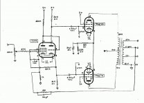
So, why am I pestering ya'll with this project? Well, there's one resistor that stumps me completely. Have a look at the attached schematic and focus on the 180k screen resistor strapped between pin 3 and pin 8 (cathode #2) of the 7199. 😕 This topology is something I've never seen.
I've checked the wiring several times, it's the same as shown for both channels. I'm hoping that somebody can help me understand this bit of screen circuit magic?
Pie-eyed and puzzled,
LarryO
I've been disecting an old tube amp of unknown origin or manufacture. Looks like it's from a console or organ. The power supply is unremarkable; classic voltage doubler (SS diodes) followed by a 4-section RC pi filter network.
The fun was tracing the circuit path as there are no tube markings whatsoever. The odd pin-outs were a bit puzzling at first, but they eventually helped identify the tubes that were intended by the designer.
Mostly the topology is straight forward; pentode gain stage followed by a split-load phase splitter driving a cathode-biased grounded cathode output stage.
So, why am I pestering ya'll with this project? Well, there's one resistor that stumps me completely. Have a look at the attached schematic and focus on the 180k screen resistor strapped between pin 3 and pin 8 (cathode #2) of the 7199. 😕 This topology is something I've never seen.
I've checked the wiring several times, it's the same as shown for both channels. I'm hoping that somebody can help me understand this bit of screen circuit magic?
Pie-eyed and puzzled,
LarryO
Attachments
dhaen said:I'm guessing there is a jumper between pins 2 & 3 of the 7199 you've missed.😉
Interesting guess, but sorry, nope, no jumpers there in either channel. If there were, wouldn't that bias-up the cathode of the phase splitter and hamper its functionality?
Thanks for looking!
LarryO
Jumper?
Mmmm, maybe not. As drawn, the cathode of the phase splitter will be elevated at something like 100V. If the plate current of the first section is 1 mA or so, the screen current will be something like 0.1-0.2mA, which would put the screen at something like 80V, which is OK.
The clever bit is that there's DC feedback. If the first stage plate voltage rises, so does the cathode of the split load. That increases the screen voltage on the first stage, increasing the current, and thus lowering the plate voltage.
Wide-eyed with clarity
Bingo! I saw the negative feedback effect but got all balled up in thinking it was signal related - some how tamed the nortorious asymetry of the split load phase splitter. By Jove, I believe you hit the nail squarely on the head. The magic is in the 1.0uF cap that stabilizes the screen grid to cathode voltage of the pentode and sets the corner frequency for the low frequency servo loop. This is really a cleaver bit of design, the high gain of the pentode is utilized to ensure a stable quiescent state for both stages. Which should also help keep the phase splitter balanced, at least to the extent that the plate and cathode load resistors were choosen well and don't drift too much over time.
Thanks SY 😀
A tip-of-the-hat,
LarryO
SY said:The clever bit is that there's DC feedback. If the first stage plate voltage rises, so does the cathode of the split load. That increases the screen voltage on the first stage, increasing the current, and thus lowering the plate voltage.
Bingo! I saw the negative feedback effect but got all balled up in thinking it was signal related - some how tamed the nortorious asymetry of the split load phase splitter. By Jove, I believe you hit the nail squarely on the head. The magic is in the 1.0uF cap that stabilizes the screen grid to cathode voltage of the pentode and sets the corner frequency for the low frequency servo loop. This is really a cleaver bit of design, the high gain of the pentode is utilized to ensure a stable quiescent state for both stages. Which should also help keep the phase splitter balanced, at least to the extent that the plate and cathode load resistors were choosen well and don't drift too much over time.
Thanks SY 😀
A tip-of-the-hat,
LarryO
I'd never seen this idea before. Thanks for tracing it out and posting it.
The "notorious asymmetry" is an audio Urban Legend. If symmetrically loaded, which is the case in any practical amp, a standard split load has balance as good as the matching of the load resistors.
The legend's root is the naive attempts to measure this. The audiophile sticks a scope first across the cathode, then the plate, and sees different signals. Of course, in each case, the scope unbalances the load... If you couple the split load to a push-pull driver stage and measure the outputs at THAT stage, you'll see that the symmetry is near-perfect if the load resistors are well-matched.
I think there may be a bit more going on in this circuit than has previously been commented upon. The split load phase-splitter has been deliberately unbalanced, which will cause the drive to the output stage to be unbalanced, causing it to cancel second harmonic distortion imperfectly. At the same time, there is a harmonic equaliser resistor (the unbypassed 180R in the output valves' cathode circuit), which will reduce third harmonic distortion (and possibly, but not necessarily, second). All in all, a carefully tweaked circuit deliberately engineered to favour even harmonic distortion over odd.
Is the 180K resistor removed from AC consideration because of its return to the feedback summing point?
There is more info regarding that config at www.triodeel.com/7199.htm
I've tried that trick of feeding that screen of the pentode section from the cathode follower o/p.........it works but I get considerably more thd when compared to the basic pentode configuration
(which is just as fussy setting up g2 volts for min thd).
......the above problem more to do with recent makes i.e Sovtek types.........but using NOS RCA 7199 the effect is far smoother.
I find Sovtek makes benefit from a 1K2 in the cathode of the pentode stage instead of 820R specified.
On merit I'll give this little tube 9/10 for having all in one piece of glass.
When designing phase splitter stage with tis tub.....the cathodyne does suffer from unequal B+ ripple rejection from both phase o/ps........use stabilised B's or plenly of Cap.
richj
Happy to, part of the DIY fun!SY said:I'd never seen this idea before. Thanks for tracing it out and posting it.
The "notorious asymmetry" is an audio Urban Legend. If symmetrically loaded, which is the case in any practical amp, a standard split load has balance as good as the matching of the load resistors.
The legend's root is the naive attempts to measure this. The audiophile sticks a scope first across the cathode, then the plate, and sees different signals. Of course, in each case, the scope unbalances the load... If you couple the split load to a push-pull driver stage and measure the outputs at THAT stage, you'll see that the symmetry is near-perfect if the load resistors are well-matched.
Hhmmm, unplug the output tubes, put a scope probe on each grid-pin connection (>1Mohm||11pf), watch trace A and B, use V-pos to overlap traces. . . So where's the imbalance due to measurement? [yes, dual trace scope is assumed, but single trace could also be used if one has two probes on hand]
Have fun,
LarryO
SY said:Is the 180K resistor removed from AC consideration because of its return to the feedback summing point?
Hhmmm, why wouldn't there be 1/181 volts of feedback (-45dB from the triode's cathode) presented to the feedback summing point on the pentode's cathode?
LarryO
lgo51 said:
Hhmmm, why wouldn't there be 1/181 volts of feedback (-45dB from the triode's cathode) presented to the feedback summing point on the pentode's cathode?
LarryO
It's a bit more complicated because the cathode resistor is paralleled by the 'looking in" impedance at the cathode and the fed back signal via the 18K resistor. It might be fun to draw out the equivalent circuits and see how much AC feedback there really is.
- Status
- Not open for further replies.
- Home
- Amplifiers
- Tubes / Valves
- Pie-eyed and puzzled...