My Simple SE

Great job! Nice mirror finish. How did you achieve this?
Kind regards
Michael
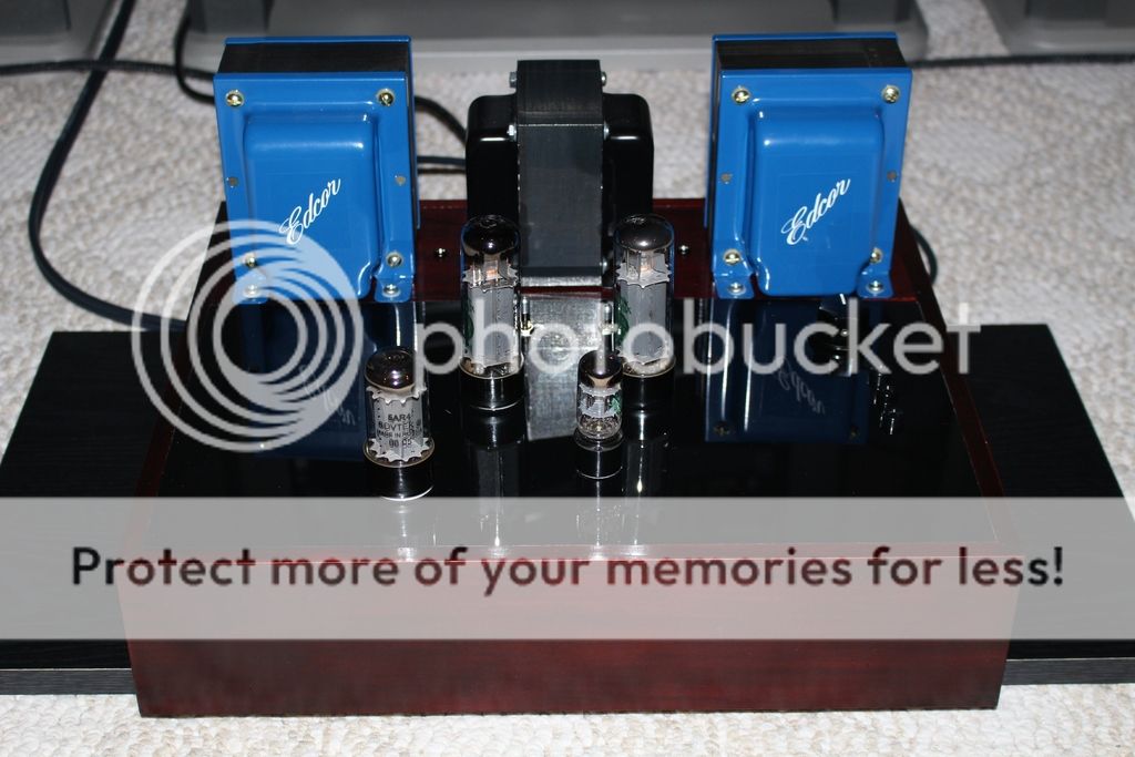
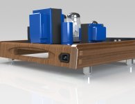
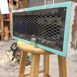
Thanks Michael. There is wood and supports under the transformers. The area around the tubes has a Lexan cover. Lexan is a type of plastic. I purchased clear and then spray painted the underside black. The top provides the clear glossy finish look.
I was worried about the heat at the base of the tubes, but so far so good. Lexan was not my first choice, I actually like other types of acrylic plastics. However, the Lexan was available.
I was worried about the heat at the base of the tubes, but so far so good. Lexan was not my first choice, I actually like other types of acrylic plastics. However, the Lexan was available.
An automatic center punch?
I did not know those spring loaded punches are considered to be 'automatic'.
I have one...it automatically moves as I pull up on it 😀😀😀
What works for me is making a mark with a regular scratch awl and a hammer then drilling an 1/8" hole, carefully riding the trigger until the bit bites with my cordless. That makes a perfect guide for the hole saws or stepped bit in the drill press.
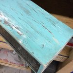
Skidave, you are better off with the lexan than acrylic. Acrylic softening point is 80C. Lexan is polycarbonate, softening point 150C. Much tougher too and easier to cut without chipping or cracking.
Sent from my HTC One_M8 using Tapatalk
Sent from my HTC One_M8 using Tapatalk
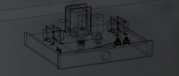
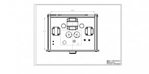
Well here are the layout drawings of my SSE so far, I've plenty of time to play around with the chassis layout because I won't have money for the transformers or tubes for a few months yet.
I've drawn it with the Edcor XPWR059, GSXE Edcors and GL KT88's and
2 auxiliary capacitors (I presume I just wire them in parallel?)
Walnut back and sides and 1/2" aluminium plate front panel.
I have a Blue Velvet 50K pot for the front.
I will probably cut a few Lexan top plates first to check fit before I cut the top Alu plate.
I cut the 1/2 front panel today with my router and it did not like it much!
I think I may have the interconnects on the wrong side?
Any comments or corrections appreciated as I haven't really got my head around the wiring part of it yet.😕
George
Attachments
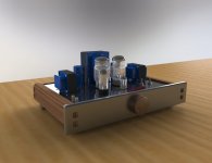
I don't see any layout drawings. All I see are a 3D wireframe model and photorealistic renderings of that 3D wireframe model. A layout drawing by definition consists of top front and side views and perhaps dimensions of the layout.


I don't see any layout drawings. All I see are a 3D wireframe model and photorealistic renderings of that 3D wireframe model. A layout drawing by definition consists of top front and side views and perhaps dimensions of the layout.
ooh!
Here's a top view, I don't think a front and side will add much.
The 2 switches on the right are the power and tube rectifier.
The interconnects are on the left I think I need to switch them.
If I place the aux caps like that will I have a lot of wires crossing under the board causing hum problems?
Back in the 70's while attending college I started out working as a Design Draftsman on a drafting board. Since then I've gone on to work as a Senior Aerospace Engineer using CADCAM software as a tool for performing my tasks. I consider myself to be a Master Draftsman due to my extensive experience. Sorry for pointing out the technicality.
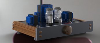
By the way ...your design is very nice. It's giving me a few ideas.
By the way ...your design is very nice. It's giving me a few ideas.

 Heres a different theme. Bought the chassis at a hamfest last week for 2 bucks with an OEM RCA 12at7 for 2 bucks.125 ESE Hammonds are hanging from the top of the chassis.Reused power trans from an Olson integrated amp.450 volts B+ solid state.I used 4 560ufd caps each pair in series for caps 2 and 3 (plus a large choke)and a solen 10ufd 630 volt for cap 1 I had laying around.The Hammonds have surprising bass and a nice top end for what they cost (35/apiece in 2003)Works perfect at 3hours of life so far.
Skidave, you are better off with the lexan than acrylic. Acrylic softening point is 80C. Lexan is polycarbonate, softening point 150C. Much tougher too and easier to cut without chipping or cracking.
Sent from my HTC One_M8 using Tapatalk
Thanks for the info gcom!
Polycarbonate is the material they use to make aircraft windshields ....or so i thought I heard.
Hi
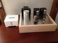
Here's what I call my SSSE (Super Simple Single Ended). It only has an on-off switch which is part of the fused power socket. It is being driven by a Sonos which controls the volume. It sounds great. I need to finish the woodwork and I think I will add a volume control so I can use my cd player, but then I think I'm done.
It has:
an Allied power transformer
Transcendar 10 watt output transformers
JJ 34L tubes
I have a question. I believe the set up I'm using is UL with CFB. As I said it sounds great. How would the amp sound different in triode mode,with or without CFB, etc? Any reason to mess with success?
This was my first build since a I built a Heathkit radio back in high school. I was amazed (and my wife very impressed) when I plugged it in, turned it on and it produced wonderful music.
Thanks George for a great amp. Your instructions are clear and easy to follow. I've learned a lot in the process.
Thanks to everyone for all the information that is on the forum.
Jacques
http://www.diyaudio.com/forums/attachment.php?attachmentid=537080&stc=1&d=1457822360
Attachments
Hi
I have a question. I believe the set up I'm using is UL with CFB. As I said it sounds great. How would the amp sound different in triode mode,with or without CFB, etc? Any reason to mess with success?
A lot depends on the speakers you are using. If your speakers are 95db or better I would definitely want to hear what they sound like in triode mode.
Jacques,
Triode mode will provide less power vs UL. The sound is different - will you like it or not? - Depends on your listening preferences. 🙂
Triode mode will provide less power vs UL. The sound is different - will you like it or not? - Depends on your listening preferences. 🙂
Jacques, I have 91 db JM Lab speakers, 2-way MTMs, that are fine with a ~7 watt per channel Tubelab SE 300b. It will depend on how easy to drive your speakers are, but with 5 or 6 watts of a triode wired EL34, I think you'd be fine. It might not be as loud, but the tone and detail might be different.
- Home
- More Vendors...
- Tubelab
- Pictures of your Tubelab amp