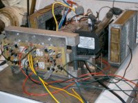
This is what I have accomplished so far with my amp. I have the channels running, but the cooling block, transformer, fans, bridge, and filter caps are not yet mounted (but I would bet they will be tomorrow). Also, the mains wiring and plumbing are not yet complete. The two Leach amps seen here are only two of the 6 channels the amp will have upon completion. I'm still waiting for some ordered parts in order to complete those channels, which are partially of my own design, but are heavily based on ESP Project 3A. They will have +/-35V supply (separate transformer) and will be capable of about 200W (but I'm thinking of using 2N5686/2N56484 on two of them to really get some power into low impedances). The boards for these measure about 2" x 5", and will be mounted on another cooling block in front of the Leach amps. Their incompletion is the main reason why so little progress has been made, I really wish my parts would hurry up. That, and I have been working on my speaker boxes and also dabbling in some other most interesting things (high energy pulses, I got a defibrillator capacitor and some other large caps the other day, but am still working on a good way to switch 25kA @ 6kV😀 ).
The front and top panels of the amp are made of a very shiny silver anodized aluminum. The front pannel includes a power switch, master volume, levels for bass, mid, and trebble, recessed levels for each channel, stereo/mono/left mono/right mono, balance, input selector, clipping and power lights, 1/4" headphone jack, (hopefully) VU/PPM meters, and maybe anything else anyone can think of. There will also be the capability to switch defferent channels around to different active crossover outputs, and these outputs will also have RCA plugs on the back. Total RMS power output from this amp could easily exceed 1kW, but it will never do anywhere near that for the speaker system I'm building now. There should always be room for upgrades though.😀
The front and top panels of the amp are made of a very shiny silver anodized aluminum. The front pannel includes a power switch, master volume, levels for bass, mid, and trebble, recessed levels for each channel, stereo/mono/left mono/right mono, balance, input selector, clipping and power lights, 1/4" headphone jack, (hopefully) VU/PPM meters, and maybe anything else anyone can think of. There will also be the capability to switch defferent channels around to different active crossover outputs, and these outputs will also have RCA plugs on the back. Total RMS power output from this amp could easily exceed 1kW, but it will never do anywhere near that for the speaker system I'm building now. There should always be room for upgrades though.😀
Attachments
Neat-o. That is some monster piping in the water blocks. You've probably mentioned this before, but what did those come out of?
I'm not really sure what those square pipes were originally used for, but I might guess some sort of frame. I got them from the recycling place (great place for bargain shopping😀 ) from their selection of scrap aluminum. They are about 1 1/4" square (as you might guess) and at least 1/8" thick. They have all different sizes up to really big ones like what I'm mounting my TO-247s on for the big amp. I also got the heater cores there. The clear vinyl tubing and elbows are standard equipment from the hardware store, and the pump is a 500GPH from Petsmart.
The ends of the pipes are just thin aluminum (about 1mm) glued on to the ends with epoxy, and there is a coiled up aluminum wire inside the pipes to cause turbulence, increasing the efficiency of the cooling system.
The ends of the pipes are just thin aluminum (about 1mm) glued on to the ends with epoxy, and there is a coiled up aluminum wire inside the pipes to cause turbulence, increasing the efficiency of the cooling system.
Member
Joined 2002
DUde your nuts that is like super cooling haha your gong to need a fork lift to move your amp around..
i bet it will be a good soundin one ..
..j'
i bet it will be a good soundin one ..
..j'
Naaa, the two transformers together weigh about 45lbs, and that's the biggest part of the weight. It'll be heavy, but I bet not more than 100lbs even when it's full.
Yeah, that's a lot of cooling, but the devices should last a really long time, and less heating = less derating = more power. The thermostat that turns on the pump and fans will close at only about 55°C. I might go higher if I find the noise too loud.
Yeah, that's a lot of cooling, but the devices should last a really long time, and less heating = less derating = more power. The thermostat that turns on the pump and fans will close at only about 55°C. I might go higher if I find the noise too loud.
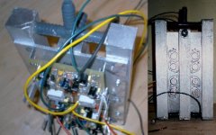
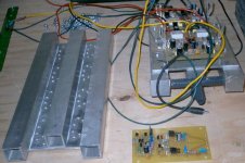
Here's the block for the other 4 amps that I made a few days ago (but the plumbing isn't done) next to the Leach amp block, and one of the boards, which I'm still waiting for parts for. It's a CF design, the Vbias transistor will mount on a common heatsink that the drivers will mount to. There's no use putting this on yet, because it will come up over the board where I still need to solder some other stuff.
Attachments
Looks cool Kilowatt.
But will the amp keep cool ??
How does the rest of the cooling system look like ?
grtz
Simon
But will the amp keep cool ??
How does the rest of the cooling system look like ?
grtz
Simon
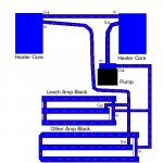
Like the picture at the top of the thread. You can see all the major components in it. Water will be pumped through the blocks in parallel, and through two 6" x 8" automotive heater cores in series by a 500GPH pump. Behind each heater core is a 4 1/2" cooling fan (they're nothing extreme, maybe I'll have to get more powerful ones). There will be a sort of shroud around each fan and heater core so that the air can go through the entire heater core, but nowhere else. Schematically, it would look like this.
Attachments
Very nice!
You attached the plate aluminum to the square tubing the same way, with epoxy?
My brother claims he can get some square copper, so I might try that ... soldering would be easy and fairly secure.
Are these square pipes thicker than say the ones at Home Depot?
You attached the plate aluminum to the square tubing the same way, with epoxy?
My brother claims he can get some square copper, so I might try that ... soldering would be easy and fairly secure.
Are these square pipes thicker than say the ones at Home Depot?
No, I didn't just epoxy the square tubes to the plates, it would have too much thermal resistance. I screwed them on tightly with sheet metal screws and there is heatsink compound between the two. The screw holes and screws are sealed with epoxy though. The square tubes are a little over 1/8" thick, I'm not sure what they have at Home Depot. Are they that thick? I got mine at Pacific Recycling in Billings, MT, but I bet no one here lives anywhere near there.😉
Blu_line, if you read the posts ("Behind each heater core is a 4 1/2" cooling fan") and looked at the picture, you would know that there are fans behind the heater cores.
P.S. Only about $300 left to go, and I will have everything to complete the amp!. I thought it would be $150 though. Interesting how these things get so pricy.
If my back-ordered parts don't come within about a week,😡 I'm going to either get equivalents that are in stock or find somewhere else to get them. I only need a few resistors and capacitors.
The leach amps don't run hot when run with audio signals..even at full volume. The only time it get really hot is when you run a constant sine wave test into a really low impedance. Liquid cooling is not really necessary. Are those heater cores used as heat exchangers? Where is the warm air that is being blown across them going? It looks like onto the transformer. I have a two channel Leach SuperAmp and it only requires conduction cooling. They have fans but they are not necessary unless you run super low impedances with constant sine waves. Good Luck though. They do sound great..regardless of the cooling method. Keep a close hand on noise generated by that pump!!!
BeanZ
BeanZ
Yes, the heater cores are used as heat exchangers from the liquid to air. The fans behind them blow through them to the outside, not suck through them like a car or like my big amp.
I am only doing this because I initially didn't want to pay high prices for heatsinks, but I ended up paying just as much or more for this setup between the pump and the plumming. I must say though that it is easier to find the stuff for water-cooling.
The cooling system will have to switch on at a temperature where the amp can be assumed to be at fair volume, so you won't hear the pump and fans. There will be a thermostat on each block, and the other amps will probably usually be responsible for the switch-on, as they will likely produce more heat, they are more of them on the block. I did notice that when I was testing the Leach amps (with no cooling), they didn't get that hot even after a few minutes at moderate volume. You can't cool a class AB amp too much though.
You may want to use something that has a higher heat capacity than water. You can add propylene glycol and that will help to transfer more heat away. I see now with the heatsinks, there is not much thermal mass there. What kind of safety is assured if a water hose breaks? Is there any protection on the AC mains for this type of catastrophic failure? The Superthane hose that you appear to have used is pretty strong stuff but you never know. A fire could occur is AC Mains circuitry get wet. Keep going!!!
BeanZ
BeanZ
Of course there will be safety devices in case of leakage or pump failure. There will be a thermostat on each block to shut down main power (I can't do each transformer individually, because the Leach amps and two of the other amps run on one transformer (+/-56V), and the other two amps have lower gain and run on the other transformer (+/-35V) for lower impedance loads or lower power). There will also be a moisture detector on the inside of the bottom panel, and it is highly unlikely that any electronics would get wet even if a hose did break unless the pump was running (which is unlikely with 1/8" vinyl, it's tough stuff). I may consider an internal GFI just in case though.
Water is a better heat conductor than antifreeze, it's just that antifreeze doesn't freeze and stuff doesn't grow in it. The solution I'm using contains mostly water, but also antifreeze, and a small amount of alcohol, and also a little detergant to lower surface tension. I forgot the exact proportions, but if I need to make more, I can just look it up on another thread entitled "Water-Cooled Audio Circuitry."
Water is a better heat conductor than antifreeze, it's just that antifreeze doesn't freeze and stuff doesn't grow in it. The solution I'm using contains mostly water, but also antifreeze, and a small amount of alcohol, and also a little detergant to lower surface tension. I forgot the exact proportions, but if I need to make more, I can just look it up on another thread entitled "Water-Cooled Audio Circuitry."
I haven't worked on the amp for awhile (but I bet no one missed me🙂 ), I have been doing other electric stuff (high voltage pulsed power), sort of a much-needed vacation from audio and amp bulding, but I will get back to it some now and hope to have all channels of the amp running within an month's time (but maybe that's a bit optomistic). I have too many big projects going on, and not the time to work on them all.🙁 And I have never been known to be the fastest progress maker anyway. 🙄
I have completed one modified p3A board though, just need to put in the Vbias diode and put in on the OPS, and I'll be ready to test.
I have completed one modified p3A board though, just need to put in the Vbias diode and put in on the OPS, and I'll be ready to test.
Unless you're truely worried about freezing, using distilled water and WaterWetter is the way to go. Also, if you do some google searches you can find ways to use a hall effect sensor to read the rate of water flow in your water line 🙂.
Yes, it would be quite nice to be able to monitor flow rate. In fact, I think I will put various jacks on the back of the amp to monitor things like temp, flow rate, power, etc.
I'm not too worried about freezing (actually I am a little, it gets somethimes -10F outside in the winter), but I am worried about stuff growing in the pipes.
I'm not too worried about freezing (actually I am a little, it gets somethimes -10F outside in the winter), but I am worried about stuff growing in the pipes.
- Status
- Not open for further replies.
- Home
- Amplifiers
- Solid State
- Pictures of my amp (not nearly complete)