
Rarkov said:Just to push my luck, what is that into 4 Ohms? Is it possible to see if it is stable down to low impedances? EG 1 or 2 Ohms?
Thanks,
Gaz
OK, I've done some simulations on this too. It seems OK to
use a 4 Ohm load, which will give you approx. 350W. This
should still be safe with proper cooling. Max drain current peaks
at 6.6A, the dissipated power per device is 120W in the peaks,
but should be well below the 100W limit on the average, even
measured only during the active half cycle, so I suppose this
is OK. Still, I would not recommend stressing it so close to
max operating conditions other than for brief periods, and if
you try, don't forget the earplugs.
You should not try to use a 2 Ohm load without adding more
output devices. The ouput power at max drain current is only
approx 200W, and each output device will peak att 240W
each in dissipated power. Don't try this at home

Once again, all results are approximate since they rely on the
accuracy of the transistor models.
Hi,
I am someone who puts alot of faith in SPICE - so that's good enough for me! Thanks so much for doing all that!
As it happens, I couldn't get hold of the MPS8599 so I also used the 2N5401/2N5551 for the diff pairs. Randy said it would have slightly higher noise but would be negligable.
It seems like it more of a power house than I thought! Thanks very much!!!
I'm building a temparary preamp now! I should be able to give you a better idea of it's sound soon!
Thanks,
Gaz
I only have one set of the Hitachi transistors, I'm using Exicon's (Profusion) instead. I wonder if they have better characteristics, or even better yet, SPICE models.
Where did you get your spice models?
Where did you get your spice models?
Interesting .. how does this relate to THD? I guess I should know that. 😕
One of the things that impressed me about Sloan's work is that he does quote the 20Khz THD figures, which are usually much higher than the 1Khz figures.
One of the things that impressed me about Sloan's work is that he does quote the 20Khz THD figures, which are usually much higher than the 1Khz figures.
Hitachi models, courtesy Fred in his previous reincarnation as HH
http://www.diyaudio.com/forums/show...ight=Hitachi mosfet spice models&pagenumber=2
Exicon was very kind providing models for their equivalents
when I mailed them. www.exicon.com choose Contacts, mail
customer service.
There are some slight differences between the Hitachis and
the Exicons according to the data sheets. I don't remember
exactly which ones, but I think the Exicons are rated at
8A max drain current, and the Hitachis at 7A.
I tried to serach this forum and audioasylum a while back for
info on comparisons. I found only one person who reported
listening tests, and he had a slight preference for Exicon.
Rarkov said:As it happens, I couldn't get hold of the MPS8599 so I also used the 2N5401/2N5551 for the diff pairs. Randy said it would have slightly higher noise but would be negligable.
I have wondered why he used those particular transistors, and
I suspected it could have to do with noise. I don't think that
will make much of a difference in a power amp. Otherwise I
think you could replace them with BC550/BC560 which are
low noise version of the usual BC547 etc. They should be
easy to find and won't cost much.
The parts I got from Exicon had slightly higher voltages also. I don't have any heatsinks (Tuesday!) so even a bench test is impossible yet, although I'm getting close.
Thanks for the pointer to the models for the Mosfet's.
Can you upload the spice model for the whole circuit?
Thanks for the pointer to the models for the Mosfet's.
Can you upload the spice model for the whole circuit?
jgwinner said:Interesting .. how does this relate to THD? I guess I should know that. 😕
Each of the harmonics can be read off the spectrum. Find the
difference in dB between the fundamental and the harmonic
you're interested in. Then you can recompute to percents
using that each -20dB is a division by 10, eg. -20dB is 10%,
-40dB is 1%, -60dB is 0.1%. More precisely, if d is the difference
in dB, then the distorsion is 10^(d/20), or 10^(2+d/20) if you
want it in percents.
THD is a bit harder to get, since you have to consider all
harmonics at once. I don't bother about that. I think it is
more useful to know the value of each harmonic individually.
jgwinner said:Can you upload the spice model for the whole circuit?
I only have it the SwCAD3 file format, so it won't be useful unless
you use this implementation of Spice. Alternatively, I could just
extract a standard Spice netlist from it, but it will be without
comments on which component is which in the diagrams.
Component numbera are different from Sloanes schematic since
SwCAD numbers them automatically when entering the schematic.
I just realized that I could post my version of the schematic
along with the netlist, so you can see which component is
which. The netlist is autogenerated by SwCAD so you may have
to do some editing to get it working, perhaps.
There are a few additional resistors not in Sloanes original.
These are only for testing purposes. Some are set to 1 microOhm
and used only to be able to measure the current at these
particular points. The others are set at 1 GOhm in order not
to interfer. I used the latter to experiment with extra loading
on the VA stage.
Netlist follows:
* D:\Program\LTC\SwCADIII\Optimos2.asc
Q1 N004 N011 N008 0 2N5401
Q2 N003 N009 N001 0 2N5401
R1 N007 N006 2.7k
R2 N005 N006 1k
R3 N002 N001 100
R4 N002 N008 100
R5 N009 0 10k
Q6 N013 N032 N012 0 2SD669
R7 N011 N014 1µ
R8 N011 N015 10k
C2 N014 N015 10p
R9 N011 N016 270
C3 N016 0 220µ
V1 N010 0 SINE(0 0.95 1k) AC 1
C4 N010 N009 22µ
V2 N024 0 42
V3 0 N006 42
R10 N022 N024 1k
R11 N021 N024 2.7k
R12 N018 N017 100
R13 N018 N023 100
Q8 N020 N009 N023 0 2N5551
Q9 N019 N011 N017 0 2N5551
I2 N024 N002 1.5mA
I3 N018 N006 1.5mA
Q12 N037 N026 N025 0 2SB649
Q14 N038 N029 N037 0 2SB649
Q15 N041 N042 N013 0 2SD669
C1 N030 N027 180p
C5 N026 N030 68p
C6 N032 N031 68p
C7 N031 N028 180p
R18 N031 0 1k
R20 N027 N034 680
R21 N028 N035 680
R24 N036 N015 0.22
R27 N015 N033 0.22
R31 N015 0 8
R32 N038 N027 1µ
R33 N028 N041 1µ
XU1 N024 N034 N036 2SK1058
Q13 N022 N039 N019 0 2N5551
Q16 N021 N039 N020 0 2N5551
V6 N039 0 24V
V7 0 N040 24V
R14 N030 0 1k
R17 N024 N025 100
R15 N027 N028 200
R6 N012 N006 100
C8 N027 N028 100µ
R16 N024 N029 6.8k
R19 N029 N015 6.8k
R22 N015 N042 6.8k
R23 N042 N006 6.8k
Q3 N007 N040 N003 0 2N5401
Q4 N005 N040 N004 0 2N5401
R25 N027 N043 1G
R26 N043 N028 1G
XU2 N006 N035 N033 2SJ162
R28 N026 N021 1µ
R29 N032 N007 1µ
R30 N027 N045 680
R34 N047 N015 0.22
R35 N015 N044 0.22
XU3 N024 N045 N047 2SK1058
XU4 N006 N046 N044 2SJ162
R36 N046 N028 680
.model NPN NPN
.model PNP PNP
.lib D:\PROGRAM\LTC\SWCADIII\lib\cmp\standard.bjt
.tran 0 2m 0 10u
;op
;ac dec 10 1u 1G
;dc v1 -2 2 .01
* Load
* Input
.lib 2sj162.mod
.lib 2sk1058.mod
.backanno
.end
Attachments
Hi,
I will draw up an orcad or Protel circuit if there is any interest / need. Strangely enough, I am using Exicons. They were the only equivilents I could get. They were about £4 each...
Thanks
Gaz
I will draw up an orcad or Protel circuit if there is any interest / need. Strangely enough, I am using Exicons. They were the only equivilents I could get. They were about £4 each...
Thanks
Gaz
Fantastic ..
I'm using SWCAD also, or at least I had a copy installed somewhere. I know what you mean about renumbering, I was trying to very carefully add each part in the same order as Sloan was using, but only got about half way there.
My wife said "Build it already" and she was right so I quit simulating and just started soldering 😀
Sloan's THD figures seem to be lower than your simulation, which depresses me a bit.
Have you measured yours?
I used his boards, but I'm not sure I can measure THD with just a voltmeter / sound card. I don't have an oscope (yet).
I have an oscillisope...just bought one from Ebay - but no knowledge of how to measure THD...Where can I buy that from?!
Gaz
Gaz

- Status
- Not open for further replies.
- Home
- Amplifiers
- Solid State
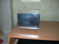
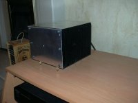
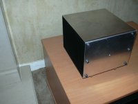
- PICS: "Optimos" 140W Monoblock Amps!