Single Dac circuit
Rarkov ,
the schematic you link at is uncorrect IMHO:
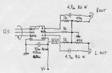
the 47k resistor must be connected at the signal output after the caps and at ground , while in the picture they are connected at ground and at the ground of the output pin
I also use filter the high freq with a cap across the 1k I/V resistor : my first set is 2.2n but I suspect that I will prefear a 12db/oct slope; more listening will tell me what to do .
Rarkov ,
the schematic you link at is uncorrect IMHO:
the 47k resistor must be connected at the signal output after the caps and at ground , while in the picture they are connected at ground and at the ground of the output pin
I also use filter the high freq with a cap across the 1k I/V resistor : my first set is 2.2n but I suspect that I will prefear a 12db/oct slope; more listening will tell me what to do .
Attachments
Member
Joined 2002
It is a D/A converter ,the TDA1543, that accept I2S signals format at the input (at the left) ;
It is complete of a passive I/V converter (pin 6,8) output stage , and a resistor ,1K at pin7 ,for a voltage reference that is essential for the DAC circuit.
It is complete of a passive I/V converter (pin 6,8) output stage , and a resistor ,1K at pin7 ,for a voltage reference that is essential for the DAC circuit.
stefanobilliani:
I will try and look into your points about the schematic. I hope they're correct, but easy to fix if not! Thankfully! 😉
I haven't been able to run the DAC yet (as it solely accepts I2S) but when I ordered the CD-PRO2 uint - the bloke said that the onboard DAC is excellent...so it's just a case of trying them I think.
I've just checked the datasheet and nothing was mentioned about output stages...I'll ask Peter Daniel...
Thanks,
Gaz
Re: Single Dac circuit
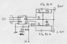
Yes, the 47k resistors are connected on a schematic between 2 grounds, which doesn't make sense. They have to go from output to ground as mentioned in a post. They are only there to discharge the caps and I'm not using them at all. You may expect a thump in a speakers when powering on and off, but my DAC is always on so I don't worry about it. In the Kusunoki schematic, there were some caps across 1k resistors (3.3n), but I decided not to use them. The DAC works fine without them and sounds great. I'm using Rikens for I/V resistors and 3.3 u MIT RTX for coupling caps. Reclocking brought big improvement and better PS is also important . This is my currently best DAC, it's better than anything I tried with oversampling and it's also better than TDA1541 in my Marantz CD-94 (non oversampling and partly modified). It may be not the first word in dynamic, but I trade it for resolution and ambience I got with passive output stage. Here's the link to some pics: http://www.diyaudio.com/forums/showthread.php?s=&postid=175127#post175127
stefanobilliani said:Rarkov ,
the schematic you link at is uncorrect IMHO:
the 47k resistor must be connected at the signal output after the caps and at ground , while in the picture they are connected at ground and at the ground of the output pin
I also use filter the high freq with a cap across the 1k I/V resistor : my first set is 2.2n but I suspect that I will prefear a 12db/oct slope; more listening will tell me what to do .
Yes, the 47k resistors are connected on a schematic between 2 grounds, which doesn't make sense. They have to go from output to ground as mentioned in a post. They are only there to discharge the caps and I'm not using them at all. You may expect a thump in a speakers when powering on and off, but my DAC is always on so I don't worry about it. In the Kusunoki schematic, there were some caps across 1k resistors (3.3n), but I decided not to use them. The DAC works fine without them and sounds great. I'm using Rikens for I/V resistors and 3.3 u MIT RTX for coupling caps. Reclocking brought big improvement and better PS is also important . This is my currently best DAC, it's better than anything I tried with oversampling and it's also better than TDA1541 in my Marantz CD-94 (non oversampling and partly modified). It may be not the first word in dynamic, but I trade it for resolution and ambience I got with passive output stage. Here's the link to some pics: http://www.diyaudio.com/forums/showthread.php?s=&postid=175127#post175127
This points out the bad points about PCBs!!!
Oh well...Shouldn't be too difficult to change.
Just a couple of questions...
Does reclocking refer to reclocking the circuit board on the actual CD-PRO2 unit?
What defines the NON-OS or 4x OS in this circuit (or anywhere for that matter!?)
Sorry - I'm sure they're simple questions - just ones that I've never needed the answer to yet.
Thanks,
Gaz
If you add a digital filter chip it will be 4x oversampling, otherwise non-os. Peter ment asynchronous reclocking. This is reclocking with a different frequency than SP/DIF. You could contact Elso Kwak for a circuit... (see also my Nonoz page at www.fedde.tk)
Fedde
Fedde
Are OK - Thanks.
However - since this circuit is solely for the input of I2S, I would not be able to reclock the SPDIF...Have I caught the wrong end of the stick?!
Thanks,
Gaz
However - since this circuit is solely for the input of I2S, I would not be able to reclock the SPDIF...Have I caught the wrong end of the stick?!
Thanks,
Gaz
You can reclock all free lines in I2S signal. That's exactly what I'm doing with signal between Crystal receiver and DAC. And it makes a difference. You can add another small board, with a clock, reclocking chips and PS for the circuit. I'm also using a separate transformer for that. This can be added later.
Re: Re: Single Dac circuit
Try an 8V supply!
Or did I suggest that before ?
Fedde
Peter Daniel said:
This is my currently best DAC, it's better than anything I tried with oversampling and it's also better than TDA1541 in my Marantz CD-94 (non oversampling and partly modified). It may be not the first word in dynamic...
Try an 8V supply!
Or did I suggest that before ?
Fedde
Peter Daniel said:You can reclock all free lines in I2S signal. That's exactly what I'm doing with signal between Crystal receiver and DAC. And it makes a difference. You can add another small board, with a clock, reclocking chips and PS for the circuit. I'm also using a separate transformer for that. This can be added later.
I recloked an old Philips CD630 bypassing the saa7220 digital filter(4Xfs) and connecting the clock directly to the receiver saa7310.I used the Elso KC-7 ---- thanks Elso , your clock sounds great I love it!------and also the SPDIF output works better .
Peter,
I would like to learn something more regarding reclocking between the CS8412 and the TDA1543, can it be done with the CK-7 and if yes , where can I find schematics for reclocking chips?
Thanks
Hi,
I tried to connect my TDA1543 DAC to the CD-PRO2 yesterday and got noise - and only noise! I connected:
BCK to Pin 2
WS to Pin 3
DATA to Pin 4
All on jumper 1005 of the CD-PRO2 unit. Is this correct? What could the problem be? I did not reclock...Just added 5V and connected those three lines to the transport.
Thanks,
Gaz
You can measure the DC voltages of the I2S signals to see if they do something. Did you use correct I/V resistors and Vref resistor !?
Fedde
Fedde
- Status
- Not open for further replies.
- Home
- Source & Line
- Digital Source
- Pics: CD-PRO2 PSU & TDA1543 DAC