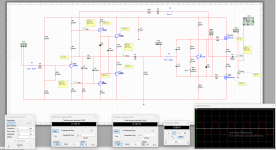
This is my favorite amplifier design for now that I am listening for 3 months and it still is good for me. In the past I build perfect clone of an Unitra Stereo Hit but it was desined with RIA correction directcly in the amplifier and for some reason I did not like it. The schematic I am posting now could have some further modifications and I have to say that I like simple designs more, I did complex stuf but to hard to repair.
Attachments

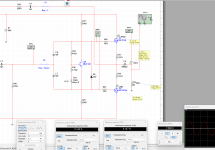
I cheked this morning what is the state of components in the driver stage and I saw some modifications C4 is 47pF and another compensation capacitor of 47 pF (C7) was there, and after this I decided to block R3 voltage with 10uF because the signal there would be 180 degres out of phase.
Attachments

Did you come up this design by yourself?
It is a way to learn in this way, but it has multiple issues.
I would suggest to stick with the "Blameless" topology for beginners.
It is a way to learn in this way, but it has multiple issues.
I would suggest to stick with the "Blameless" topology for beginners.
It is my design, just because it simple does not mean it has flaws. I am curios to hear what the flaws are to make a more clear view of what you are trying to say. I make my own designs for 10 years and I do not consider myself a beginner.
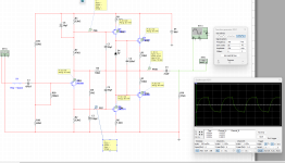
The amplifier works as I intended (to make my ears happy), and the 20 Khz atenuation is there because that is how I enjoy my amplifiers, I had 500 Khz 3db atenuation amplifiers and do not like it.
- Home
- Amplifiers
- Solid State
- Pick-Up amplifier design adapted to 80 VDC