Hi,
Finally Arduino it is running in windows 10. I did some changes to the power ON routine. I added a return every time that you branch to the delay routine and also changed the switch pinmode to input pullout. That it is to prevented the pin to be floating. That may give you random triggering. Please try it and post your finding. I will keep myself learning windows 10.
Finally Arduino it is running in windows 10. I did some changes to the power ON routine. I added a return every time that you branch to the delay routine and also changed the switch pinmode to input pullout. That it is to prevented the pin to be floating. That may give you random triggering. Please try it and post your finding. I will keep myself learning windows 10.
Attachments
Relay1 now toggles on-off-on followed by normal delay sequence
I assume the input pullup on the power switch is doing this
I added the INPUT_PULLUP to the revision in post 100 and it seems to initially work.
I assume the input pullup on the power switch is doing this
I added the INPUT_PULLUP to the revision in post 100 and it seems to initially work.
Last edited:
This should operate the relays. LED operation is a couple more simple function calls. Shutdown order can be rearranged by changing the order of the "digitalWrites" in the "powerOff" function call. Delays can be added for shutdowns there as well. A voltage detector function call needs to be added yet too (that's just a cut and paste). Let me know if you want to use the code and I'll add all the extras.
Attachments
Hi,
Attached it is the program with new modifications. First I modified the delay routine to set the on_off flag =1 and then do a return, This will aborted the delay routine immediately . The return instruction will take us back to the power on routine. In the power on routine we will check the on_off flag =1 and if it is set then we will aborted the power on routine and take us to the read switch routine. In the read routine we will check the switch and if the on_off flag = 1 and if the switch =0 then that will send the program to the power off routine and turn off all the relays. I removed the read switch instructions in the power on routine since we are checking it in the delay routine. Right now it is working OKAY in my test jig with 4 leds lights. Check it out and report your findings. Hoped you understand the above explained. I don't. Just kidding.
Attached it is the program with new modifications. First I modified the delay routine to set the on_off flag =1 and then do a return, This will aborted the delay routine immediately . The return instruction will take us back to the power on routine. In the power on routine we will check the on_off flag =1 and if it is set then we will aborted the power on routine and take us to the read switch routine. In the read routine we will check the switch and if the on_off flag = 1 and if the switch =0 then that will send the program to the power off routine and turn off all the relays. I removed the read switch instructions in the power on routine since we are checking it in the delay routine. Right now it is working OKAY in my test jig with 4 leds lights. Check it out and report your findings. Hoped you understand the above explained. I don't. Just kidding.
Attachments
Looks like you started to use milli's for delay in the main loop and didn't finish?
Not sure if that will work with the power on code. I'll test it tonight
Not sure if that will work with the power on code. I'll test it tonight
Hi,
Yes, finally I took jwilhelm advised. It is was not too hard to learned it. You need to change the delays to seconds now. Now the delay routine will terminate immediately you turn OFF the switch. No 5 seconds delay. Everything worked for me using my test jig. I have 4 led for relay 1,2,3 and 4 that are turn ON following the program sequencing with no problems. Also the program it is more clean. Slowly I am learning how to program the Arduino.
Yes, finally I took jwilhelm advised. It is was not too hard to learned it. You need to change the delays to seconds now. Now the delay routine will terminate immediately you turn OFF the switch. No 5 seconds delay. Everything worked for me using my test jig. I have 4 led for relay 1,2,3 and 4 that are turn ON following the program sequencing with no problems. Also the program it is more clean. Slowly I am learning how to program the Arduino.
One thing you need to remember when using millis is it rolls over to a negative number after 59(?) days. If the microcontroller is going to stay live all the time you need to use an "unsigned long" declaration.
unsigned long currentMillis;
Then wherever you want to reference millis,
currentMillis = millis();
if (currentMillis - ...
unsigned long currentMillis;
Then wherever you want to reference millis,
currentMillis = millis();
if (currentMillis - ...
Hi,
Slowly I am learning how to program the Arduino.
Its just lots of practice.
I have been programming for 36 years.
You find as time goes on you can model bigger and bigger programs in your head.
I once wrote a 300,000 line assembly language program.
I converted it into C# and C++ which was fun.
Hi,
Thank you jwilhelm for your advice. Yes, I am defining the time variable as = unsigned long.
Thank you jwilhelm for your advice. Yes, I am defining the time variable as = unsigned long.
Looks good at first glance except for a missing LED
StatusLED is really a fault only LED
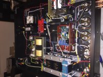
I have an LED within the power button that needs to turn on after the last Relay is energized.
Take a look at the pictures below
StatusLED is really a fault only LED
I have an LED within the power button that needs to turn on after the last Relay is energized.
Take a look at the pictures below
Attachments

Last edited:
I misunderstood. I thought you had 2 LEDs. So you have a total of 4 LEDs? I'll separate the protection led functions from the high voltage led. When do you want the ON LED to turn on?
The ON LED is tied to the Arduino power power supply. It's just status for the rear power switch and amp is ready to energize.I misunderstood. I thought you had 2 LEDs. So you have a total of 4 LEDs? I'll separate the protection led functions from the high voltage led. When do you want the ON LED to turn on?
Standby LED comes on when pushbutton is closed and sequence started, it turns off when last relay is energized.
ProtectLED is just for power issues, high voltage sensor and any faults (may add future current or temp monitoring). If this LED is on, all others should be off. The number of blinks could be programmed to indicate the fault type.
HighvoltageLED (inside of power switch) tells me that last relay is energized and high voltage is on. If fault occurs or pushbutton is opened, this LED should turn off
Right now I've written the protection LED to blink once every two seconds on over-voltage, and twice every two seconds on power failure. I'll rearrange the high voltage LED this evening.
Looks good at first glance except for a missing LED
StatusLED is really a fault only LED
I have an LED within the power button that needs to turn on after the last Relay is energized.
Take a look at the pictures below
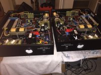
The amp looks great upside down. How about some pictures of it upright?
I'm currently doing some physical therapy on my shoulder and trying to avoid re-injury....
I might get some help this weekend to move these out for some real listening tests.
Also waiting on a couple caps to lower the voltage on the B+ rail.
Right now its about 1225 volts, I need it closer to 1100-1150v. A 5v variation on the primary could easily send this closer to 1300volts! 😱
I might get some help this weekend to move these out for some real listening tests.
Also waiting on a couple caps to lower the voltage on the B+ rail.
Right now its about 1225 volts, I need it closer to 1100-1150v. A 5v variation on the primary could easily send this closer to 1300volts! 😱
Last edited:
- Status
- Not open for further replies.
- Home
- Design & Build
- Software Tools
- PIC programming