I am putting together a power CLC for a push pull KT88 amplifier. I am using Duncan’s PSU designer to model it, see output pic.
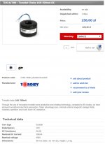
Searching for parts I have seen the Toroidy TDS16/300 - Toroidal Choke 16H 300mA DC with 66.5ohm DC resistance.
Having read a number of threads on Pi filters I came across a comment “they're toroidal core, so no adequate for DC”
Should I be looking to go low DC resistance on the inductor?
The model looks to be perfect but I know I’m missing something fundamental.
Attachments


For proper job of an inductor, the core must not saturate. For this purpose, EI laminations has a gap in the flux path, so the DC is partially canceled around iron, enabling the inductor to job without saturating. As many toroids can use higher saturation flux, possibly this choke can do the job too.
I have no experience of their chokes but they are a well regarded EU manufacturer, their transformers are high quality, they have been selling toroidal SET output trafos for a few years with high quoted mA ratings and it seems difficult to believe that since these remain available and presumably must therefore perform adequately enough for repeat sales, that they would make such a basic error in their design calculations for a choke. 400V max voltage for the choke however...
Why do you require such a high value choke ? A power amp should not require anything like 15H as a CLC/PI filter .
May I suggest that you model the PSU again with much smaller value input and smoothing caps ? Also try something like a 5H choke and try using the stepped load function which may provide insight into settling times and stability of the power supply
cheers
316a
May I suggest that you model the PSU again with much smaller value input and smoothing caps ? Also try something like a 5H choke and try using the stepped load function which may provide insight into settling times and stability of the power supply
cheers
316a
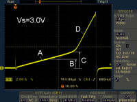
Lovely DIY article found online: Power Inductor Checker
Use an oscilloscope to measure dI/dt . This provides a measured value of inductance L.

A: inductance at low currents (core not saturated) = 21.5 uH
B: manufacturer's rated current = 1.7 A
C: onset of saturation = 3.0 A
D: inductance in saturation = 3.2 uH
_
Use an oscilloscope to measure dI/dt . This provides a measured value of inductance L.
A: inductance at low currents (core not saturated) = 21.5 uH
B: manufacturer's rated current = 1.7 A
C: onset of saturation = 3.0 A
D: inductance in saturation = 3.2 uH
_
Attachments
Last edited:
For a mains frequency power supply Pi filter the choke inductance is related to the small-signal AC current when sitting at the DC bias location on the BH curve. The ramp tester that Mark links to allows the DC level to be appreciated as core saturation licks in, but the inductance measurement does not relate to incremental inductance due to the AC ripple signal.
An example measurement test jig that can set up the DC and AC levels that a choke operates at is https://dalmura.com.au/static/Choke%20measurement.pdf
An example measurement test jig that can set up the DC and AC levels that a choke operates at is https://dalmura.com.au/static/Choke%20measurement.pdf
Sigh…
The point of a rating an inductor along the lines of “300 mA” is to identify that that is its maximum rated working current; it is not a specification of when the same core is technically in a saturated magnetic state. Usually (but by no means universally!) the saturation current of a choke is 1.5 to 1.6× that of its maximum rated DC current.
Thing to note is this: your KT–88 very most likely isn't going to be drawing anywhere near 300 mA at its optimum plate voltage. EVEN if you're implementing both left-and-right channels in one chassis.
So. Its a fine choke. 15 Hy is a stout amount of impedance, and will result in substantial line-frequency rectification-harmonics reduction. Substantial.
Myself, for the 250 mA of reasonable operating current, I'd have gone for a 1 Hy or 2.4 Hy choke.
Just Saying,
GoatGuy ✓
The point of a rating an inductor along the lines of “300 mA” is to identify that that is its maximum rated working current; it is not a specification of when the same core is technically in a saturated magnetic state. Usually (but by no means universally!) the saturation current of a choke is 1.5 to 1.6× that of its maximum rated DC current.
Thing to note is this: your KT–88 very most likely isn't going to be drawing anywhere near 300 mA at its optimum plate voltage. EVEN if you're implementing both left-and-right channels in one chassis.
So. Its a fine choke. 15 Hy is a stout amount of impedance, and will result in substantial line-frequency rectification-harmonics reduction. Substantial.
Z = 2πFL … F in Hz, L in Hy, Z in Ω
From an A/C 'harmonic' impedance point of view, Z = 2πFL
Z = 2 × 3.1415 × 60 Hz × 15 Hy
Z = 5,600 Ω
AT 60 Hz. At the next harmonic … 120 Hz, now its 11,200 Ω. At 180 Hz, 16,800 Ω. And so on. Remember, you are putting this frequency dependent impedance in series with the first reservoir capacitor's peak-holding (filtering), and another C; from a time-varying voltage perspective, capacitors have a near-zero impedance. So, if it were just resistors (and it is not!), remember your voltage divider theoryZ = 2 × 3.1415 × 60 Hz × 15 Hy
Z = 5,600 Ω
VMID = VIN • RBOTTOM / RTOP + BOTTOM… or to put numbers to it
VMID = 25 VRIPPLE(TOP) • (RCAP = 1 Ω) / (5,600 + 1) Ω
VMID = 0.00446 VRMS
Which is a pretty darn good reduction in one stop shopping. If it were resistors. Which it is not. Reality is a bit different, with the CLC filter combo having a distinctly sluggish response-over-time characteristic that some people fine objectionable. VMID = 25 VRIPPLE(TOP) • (RCAP = 1 Ω) / (5,600 + 1) Ω
VMID = 0.00446 VRMS
Myself, for the 250 mA of reasonable operating current, I'd have gone for a 1 Hy or 2.4 Hy choke.
Just Saying,
GoatGuy ✓
Cheers to all of you guy’s,
Osvaldo – thanks for the quick response. Yes, it was saturation of toroids that had got a bad press. I remembered something from another post years ago and you jogged it free.
Lots more to read and learn
@ Mark thanks for the link, definitely something else to play with. This is physical modelling and just what I need.
I think the general consensus is go for something smaller but when your modelling on software more its better and too much is just enough… and cheap.
Goat Guy – you nailed it. Thanks
Just for reference, it seems that the early Toroidy chokes didn't have an air gap and were useless for DC current, but the problem was fixed and they are OK now:
Warning about chokes by Toroidy
Warning about chokes by Toroidy
Just as an aside, the PSUD program is also not showing the overshoot of the C→L→C configuration for the first few seconds after power is turned on, but before the valves properly start conducting.
I've modeled this numerically (real discreet differential calculus!) and shown that much more modest component values are simply … just better … causing far less component stress (especially those poor, poor rectifier diodes!)
One of my favorite topologies is CLCLC, using values
Just Saying,
GoatGuy ✓
I've modeled this numerically (real discreet differential calculus!) and shown that much more modest component values are simply … just better … causing far less component stress (especially those poor, poor rectifier diodes!)
One of my favorite topologies is CLCLC, using values
47 µF → 1.5 Hy → 220 µF → 1.5 Hy → 470 µF
for the 180 mA supply-current rating your initial PSUD current sink implies. Very clean DC, modest start-up overshoot, and modest overshoot on varying load, and so on. Just Saying,
GoatGuy ✓
Last edited:
The main uncertainty I see from the first post is to do with the Toroidy ratings. Does the choke provide 16H at 300mADC, and with what AC current ?
One can't easily connect a DVM to confirm that (after buying a unit).
I can easily see the scepticism about using a standard transformer toroidal core for a choke with significant DC bias. Perhaps the core is gapped in some way, or not made of the same material.
One other design parameter that would be good to know, especially if paying a hefty price for the choke, and trying to suppress any mains related hum or noise, would be the self-resonant frequency as that is an indicator of when the shunt capacitance is starting to bypass ripple and noise.
Snax, is there a reason you have chosen a 32A diode rather than say just use a 1N4007 or UF4007 ? And is there a reason to provide such a high value of capacitance, and is the power supply for just for one channel (ie. mono amp)?
PS. the test results in the post #10 link leave just as much doubt as the Toroidy spec data.
Last edited:
Huge capacitors make nice bells. A ringing power supply from enormous load currents that get switched on and off at 100 times per second can result in a megaHertz signal running in your anodes and anywhere in your circuit close to PS wires.
Edit: The toroid core is typically a low loss unit, where a filter choke has to have the opposite property.
Edit: The toroid core is typically a low loss unit, where a filter choke has to have the opposite property.
Last edited:
That is pure nonsense.Huge capacitors make nice bells. A ringing power supply from enormous load currents that get switched on and off at 100 times per second can result in a megaHertz signal running in your anodes and anywhere in your circuit close to PS wires.
Read M Jones, Valve Amplifiers on 'Ripple current and conduction angle'. He describes an easy going 300V HT based on the GZ34 with harmonics of 2,5KHz at 45dB below the base frequency of 100Hz.
Hi GG, i like to use smaller value chokes, but, what about the problem of not having "minimum inductance", to prevent power supply ringing.Sigh…
Reality is a bit different, with the CLC filter combo having a distinctly sluggish response-over-time characteristic that some people fine objectionable.
Myself, for the 250 mA of reasonable operating current, I'd have gone for a 1 Hy or 2.4 Hy choke.
Just Saying,
GoatGuy ✓
For a mains frequency power supply Pi filter the choke inductance is related to the small-signal AC current when sitting at the DC bias location on the BH curve. The ramp tester that Mark links to allows the DC level to be appreciated as core saturation licks in, but the inductance measurement does not relate to incremental inductance due to the AC ripple signal.
Oh, I don't know about that. All of the activity on the scope trace occurs within 7.5 horizontal divisions (30 microseconds). I wouldn't call that DC.
The instrument repeats the sweep 50 times per second, which again I wouldn't call DC.
The location on the I-t curve where the dI/dt changes in a way that is characteristic of the core material entering saturation region is the appreciation of the DC level where the inductor would start encountering saturation - that is what I was commenting on. The timing is just related to the test jig voltage and inductor incremental inductance along the changing sweep of the BH curve, and the timebase would obviously be circa seconds not usec for the power supply chokes on topic.Oh, I don't know about that. All of the activity on the scope trace occurs within 7.5 horizontal divisions (30 microseconds). I wouldn't call that DC.
The core effectively starts from, and gets reset at test end to the BH origin, although there may be a bit of residual H. Those linked tests could be done at 5kHz with no change to outcome.The instrument repeats the sweep 50 times per second, which again I wouldn't call DC.
My comment is that the inductance seen by the ripple will be somewhat different from the dI/dt derived inductance taken from that tester's sweep as it passes through the DC operating current level as seen by the choke in operation.
An ordinary toroid improves inductance but does not tolerate DC well.
But Toroidy knows that, and knows toroids, so has probably figured out a technique.
I'm struggling to see "how?" I suppose they could cut the strip iron into short pieces. But that greatly complicates winding the many strips into a doughnut. Modern steel alloys can be heat-treated many ways, and they may have a special treatment to improve DC saturation without physical gaps.
Also wondering "why?" However the TDS16/300 at 4.4 pounds is lighter than Hammond's classic E-I choke 193Q 10H 500mA (similar H*I) which is 21 pounds. And the E-I is $125 while the Toroidy TDS10/500 seems to be $41??
- Home
- Amplifiers
- Tubes / Valves
- Pi Filter choke