If the off set is drifting the front end is not tracking properly.
By how much does it drift? Is the pot dirty? Does the input drift?
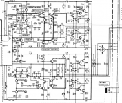
A model number would be useful to make the schematic larger and readable.
By how much does it drift? Is the pot dirty? Does the input drift?
A model number would be useful to make the schematic larger and readable.
kenwood L-01A
You might want to check the shunt regulators and the soldering ...I'd rework the whole circuit solder before doing anything else, especially the shunt power resistors.
You might want to check the shunt regulators and the soldering ...I'd rework the whole circuit solder before doing anything else, especially the shunt power resistors.
Last edited:
It's both on both channels, the trimmers are new bourns multiturn things and it's all been resoldered
It can drift upto 300mv
 phonos by chris reddish, on Flickr
It can drift upto 300mv
phonos by chris reddish, on Flickr
Last edited by a moderator:
Which is totally fine! You don't have an output capacitor and +-32V supply for nothing there.Nichicon Muse BS capacitors with less than 400mv dc on them have lower distortions than what AP can measure... Nichicon Muse ES bipolar caps measured: <-120dB THD, <-140dB IMD
Do you hear anything wrong? Do you measure that offset after the output capacitor or before that? How fast does it vary?Is it a low frequency oscillation? If i remember right the next stage is a fet input .If the output cap is good quality and that offset is not an infrasonic oscillation(which may be fine too sometimes) and it's measured before the output cap , then you should have no worries.
Do you hear anything wrong? Do you measure that offset after the output capacitor or before that? How fast does it vary?Is it a low frequency oscillation? If i remember right the next stage is a fet input .If the output cap is good quality and that offset is not an infrasonic oscillation(which may be fine too sometimes) and it's measured before the output cap , then you should have no worries.
Last edited:
I think we've had this one before. This circuit is like an input JFET 1/f noise magnifier. If both channels behave similiarly, it's probably nothing to worry about. One more reason to be engaging the subsonic filter.
I would not worry about this. The feedback networks is DC coupled, the the DC gain is very, very high. The front end uses FETs so the offset will be high and will have to be dialed out - ergo the pot. After the DC blocking cap on the output there’s no offset and no LF noise.
The lower leg of the gain setting resistor is ~23 ohms if I am reading it right - so this is probably why the DC coupled it - you would need an enormous cap to get decent LF response.
Thermal currents around the input will exacerbate the LF noise problem. Once you shield the input you should find it will decrease - just boxing the amp up should also show an improvement.
But seriously, 300 mV of offset on this is nothing.
Last edited:
- Home
- Source & Line
- Analogue Source
- Phonostage dc offset improvement