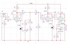
This is my first attempt at designing phono stage, or RIAA amp.
It looks to me that the circuit is quite straight forward. Each one of the 2 amplifying stages has 30dB gain @ 16mA. Accounting for the ~20dB@1KHz loss of the RIAA equalizer, makes the total gain ~40dB.
I couldn't find anywhere a way to calculate the CF cathode resistor, so I hope the value in the schematic is correct. Tubes are ordered and on their way. Also PCB design is currently in process. I have stabilized tube PSU and power transformer to do the initial tests with.
All comments are appreciated.
Attachments
Hi Joshua,
I recommend a minimum of 8.2K 10K for the plate resistors as the rp of this tube is about 2K or so, and your load resistors will result in a great deal of distortion.. Better still would be a CCS load. Bias in the range of 1.2V from an IR led is also recommended. Plate current should be >10mA to achieve relatively high transconductance with the D3A. Using 10K plate resistors will require a supply of about 250V. Expect to have to trim the 22K resistor in the RIAA equalizer in order to get the equalization right. (Typically a few % one way or the other.)
Your coupling caps are probably a bit on the small side. Note also that D3A do draw some grid current and that 1M grid resistor should probably be reduced to 220K or so, if you do this you must increase that first coupling cap to at least 0.1uF.
Depending on what you are driving you may not need the CF last stage - if the input impedance of the following stage is >20K this is certainly the case.
Last edited:
Cathode resistor of CF stage is same as anode resistor in common cathode stage. You set its value according to your desired loadline exactly the same way.
Hi Kevin,
Thank you.
What you say does make sense. The 1.3K Rp was chosen or 30 dB gain. With Rp 8-10 K the gain will be too high, 36 dB. How to compensate for it? D3a ri in triode mode is 1.9K.
Like SRPP, or what?
The present plate current is 16 mA. I remember your recommendation in another thread to set it for 10-20 mA,
Changing the value of Rp, all other values will have to be recalculated.
D3a in Common Cathode triode mode Z out is 1.2 – 1.6 K, depending on Rp. Though I may get away with it, Z out of about 25 Ohm in CF mode is highly preferred. In such a case, there are no worries about any load and any length of interconnect cables.
I recommend a minimum of 8.2K 10K for the plate resistors as the rp of this tube is about 2K or so, and your load resistors will result in a great deal of distortion.
Thank you.
What you say does make sense. The 1.3K Rp was chosen or 30 dB gain. With Rp 8-10 K the gain will be too high, 36 dB. How to compensate for it? D3a ri in triode mode is 1.9K.
Better still would be a CCS load.
Like SRPP, or what?
Bias in the range of 1.2V from an IR led is also recommended. Plate current should be >10mA to achieve relatively high transconductance with the D3A.
The present plate current is 16 mA. I remember your recommendation in another thread to set it for 10-20 mA,
Using 10K plate resistors will require a supply of about 250V. Expect to have to trim the 22K resistor in the RIAA equalizer in order to get the equalization right. (Typically a few % one way or the other.)
Your coupling caps are probably a bit on the small side. Note also that D3A do draw some grid current and that 1M grid resistor should probably be reduced to 220K or so, if you do this you must increase that first coupling cap to at least 0.1uF.
Changing the value of Rp, all other values will have to be recalculated.
Depending on what you are driving you may not need the CF last stage - if the input impedance of the following stage is >20K this is certainly the case.
D3a in Common Cathode triode mode Z out is 1.2 – 1.6 K, depending on Rp. Though I may get away with it, Z out of about 25 Ohm in CF mode is highly preferred. In such a case, there are no worries about any load and any length of interconnect cables.
Cathode resistor of CF stage is same as anode resistor in common cathode stage. You set its value according to your desired loadline exactly the same way.
Indeed, it is recommended in order to alleviate PSU burden, however, the bias may not be right for the tube. May primary concern here is to set the bias and plate current right.
Stop. Do not pass Go. Do not collect $200.
You're trying to do something VERY difficult without having even the most basic design chops (no shame in that, a phono stage is the toughest thing to design properly). Get, read, and (most importantly) understand the preamp chapter of Morgan Jones's "Valve Amplifiers." Even if you go about things differently than he does, the basics need attention before you jump in the deep end.
You're trying to do something VERY difficult without having even the most basic design chops (no shame in that, a phono stage is the toughest thing to design properly). Get, read, and (most importantly) understand the preamp chapter of Morgan Jones's "Valve Amplifiers." Even if you go about things differently than he does, the basics need attention before you jump in the deep end.
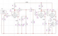
In light of some of Kevin's comments, a modified version. I had to use un-bypassed cathode resistor in order to maintain 30 dB gain with higher value plate resistor.
Not sure why 36dB of gain is an issue at all, (not that this circuit is likely to give you that much) in a world where the redbook standard of 2Vrms at 0dBFS is the normal standard for audio sensitivity the additional gain is not a bad thing. People struggled to achieve these gain levels with older passive designs - there is absolutely nothing sacred about 40dB of phono stage gain. Mine in fact has about 48dB.
You idea of using unbypassed resistors in the cathode circuit will reduce gain by > 6dB and increase your effective input noise by > 30dB which is still pretty quiet, but completely defeats the reason for using the D3A. Note also that it raises the effective rp of the tube to nearly 10K ohms - not something you really want to do. Not sure how you are modeling the D3A (whose model are you using? not mine apparently). I strongly recommend you use LED bias and not obsess about the resulting gain.. Also a CCS would normally be solid state with high performance IXYs mosfets (see the great ccs threads here, and take SY's comments to heart. He has as much experience with this tube as I do.)
What does this pre-amplifier have to drive that 25 ohms source impedance is an over-riding concern? A CF well implemented is a pretty transparent device, however here it is not really required and IMO will detract in audible if minor ways from the overall performance.
Note also that high transconductance tubes can differ very significantly in dc performance from what the simulations lead you to expect. You'll find this out right quick when you start to bread board your circuits.
Something else you should know is that you need to place the grid stoppers as close to the sockets as you can get them (< 0.75cm lead length on the grid side) I think you will also find you need stoppers on the screens - I use 221 typically here. The cathode resistor or LED leads should be very short as well. Note with the CF you should insert at least 100 ohms of series resistance in the output, placed right at the cathode - this is not a bad idea with the CC stage plate if you take from here. Very careful construction technique with short leads in a metal box is needed.
Last edited:
Stop. Do not pass Go. Do not collect $200.
You're trying to do something VERY difficult without having even the most basic design chops
Now I feel better!
To chime in: This is my introduction to the worthy D3a (just shows; age and experience is no guarantee of knowledge ...
 ).
).To topic: Looking at the graphs: Ri etc vs Ia, I notice that having an unbypassed cathode resistor takes Ri from 3,2K (10mA) to about 16K. Question: Is one not then back at an undesirable Ri (apart from feedback now improving matters slightly) with a load of >10K? Knowing that Ia has to be kept up and keeping rail voltage within bounds, one wonders what a load resistor as low as Josh had and with unbypassed cathode resistor might yield in performance - sort of working as one would a pentode - Rl < ra. (Also recognising low signal amplitude.)
Honest question without suggestion - I have not done this, and you are 'well versed' working D3as.
Now I feel better!
To chime in: This is my introduction to the worthy D3a (just shows; age and experience is no guarantee of knowledge ...
To topic: Looking at the graphs: Ri etc vs Ia, I notice that having an unbypassed cathode resistor takes Ri from 3,2K (10mA) to about 16K. Question: Is one not then back at an undesirable Ri (apart from feedback now improving matters slightly) with a load of >10K? Knowing that Ia has to be kept up and keeping rail voltage within bounds, one wonders what a load resistor as low as Josh had and with unbypassed cathode resistor might yield in performance - sort of working as one would a pentode - Rl < ra. (Also recognising low signal amplitude.)
Honest question without suggestion - I have not done this, and you are 'well versed' working D3as.
Hi Johan,
Well I think you worked it out a bit more precisely than I did (I swagged) typically rp at 20mA is in the range of 2K IIRC and probably close to 3.2K at 10mA, (I haven't checked) but the point you made about ri>ra (rp>Rp) is completely valid, and not really acceptable in triode connection. It has serious noise implications for this tube as well.
Kevin,
D3a with mu 77 in triode mode and Rp of 8-10 K have a voltage gain of 36dB, making the total net gain of the amp about 52dB, which is way too high. It's close to what's required from MC phono stage. With52 dB voltage gain, 5mV cartridge will give 2V at the output. My present phono stage, EAR 834P has 53dB gain, which is way too high, from my experience – the pre-amp's volume control has to be turned almost all the way down, with insensitivity to small volume changes. Too much gain isn't necessarily a blessing.
Also, with Zout=~1K, interconnect cables' capacitance may come onto play and influence the performance.
By stoppers to the screens, do you mean both grid 2 and grid 3?
Now, I'm aware of possible differences between calculations/simulations and an active circuits. Changes to the schematic will be made according to actual measurements on a running circuit. However I'd like to start with a schematic as close to the desired calculated results.
Your comments about construction are taken.
As for 100 Ohm in series of the output – it's on my mind all along, only the software I currently use to draw the circuit has limited width, so I omitted it from the drawing.
John,
According to the calculator I use, D3a with bypassed cathode resistor and 1.3K Rp has Z out of 772 Ohm, making Rp/ri = ~1.68. With un-bypassed 125 Ohm cathode resistor and Rp=9.1K, Z out is 5.1K and Rp/ri is ~1.78, so nothing worthwhile is gained. With Rp=9.1K and bypassed cathode resistor gives Z out=1.57K and Rp/ri=~5.8, which is much better, however, the gain is too high to my liking.
Any ideas (other than reading text books)?
Any ideas (other than reading text books)?
God forbid you should actually stoop to learning the basics like the rest of us peasants!
My article on phono preamp design should be appearing here shortly. If reading a textbook is offensive to you, perhaps an article might be less horrible. And there, you will learn how to run a D3a properly, how to bias it, how to load it, how to distribute gain, and how to supply power to it (not a trivial exercise).
Johan: The D3a is a great tube (not quiet enough for MC, but certainly quiet enough for MM), but the high gm means that precautions must be taken. When I first got one of them on my test bench, I thought my spectrum analyzer was broken because the distortion was so incredibly low.
God forbid you should actually stoop to learning the basics like the rest of us peasants!
My article on phono preamp design should be appearing here shortly. If reading a textbook is offensive to you, perhaps an article might be less horrible. And there, you will learn how to run a D3a properly, how to bias it, how to load it, how to distribute gain, and how to supply power to it (not a trivial exercise).
You got me wrong, I'm all for learning. The book Valve Amplifiers by Morgan Jones was ordered yesterday from Amazon and it will take it a couple of weeks to arrive. Also, your intended article is eagerly expected by me.
Meanwhile, all constructive comments about my design attempt will be welcomed.
My serious advice remains, put it aside for a few weeks. Read Morgan's book; it takes more than a few posts to really get the detail and complication of phono stage design (and tube design in general), and Mr. Jones will be the first to admit that the book could have been twice as long and still not cover everything. But you'll understand how to figure out the noise of what you're making, the tradeoffs of various forms of biasing, how to calculate the gain structure, why 25 ohms is not a useful target for source Z, why an SRPP is not a good idea for small signal stages, why cathode degeneration is the last thing you'd want in the first stage...
My suspicion is that you'll decide to scrap it and begin again after getting the foundations. With Valve Amplifiers well-digested, you can look over Allen Wright's designs to see a different (but equally valid) approach, while understanding better why he did what he did.
My suspicion is that you'll decide to scrap it and begin again after getting the foundations. With Valve Amplifiers well-digested, you can look over Allen Wright's designs to see a different (but equally valid) approach, while understanding better why he did what he did.
Any ideas (other than reading text books)?
SY,
I actually took that as meaning that Josh can (and does) read text books himself; what he is looking for here is what those books do not give. But no quibble; your advice is sound - er - good!
Joshua said further:
John,
According to the calculator I use, D3a with bypassed cathode resistor and 1.3K Rp has Z out of 772 Ohm, making Rp/ri = ~1.68. With un-bypassed 125 Ohm cathode resistor and Rp=9.1K, Z out is 5.1K and Rp/ri is ~1.78, so nothing worthwhile is gained. With Rp=9.1K and bypassed cathode resistor gives Z out=1.57K and Rp/ri=~5.8, which is much better, however, the gain is too high to my liking.
I am not going to indulge in(to) detailed design here (you seem to know where to get that), but just to reply to your post; it would appear that we are using different parameter data.
In the Rp = 1,3K circuit the D3a is drawing Ia = 15,4mA. Philips data sheet for µ, ri and S, vs Ip, shows that at that Ip, ri = 2,4K without cathode degeneration. In the Rp = 9,1K circuit, an Ia = 10mA is drawn. For that the datasheet shows ri = 3.2K, which rises to 5,7K with an unbypassed cathode resistor of 125 ohm. (This is different from my previous guestimate; I did not earn the compliment paid me by KevinKR!).
These values differ from yours, and I cautiously believe that one might trust data from reliable manufacturers - but as said, not to be nit-picking, just comparing. Going the right way, we should all arrive at the same result!
SY,
I actually took that as meaning that Josh can (and does) read text books himself; what he is looking for here is what those books do not give.
Possibly, but it's evident that he hasn't quite gotten what those books DO give- and without that, design consists of flinging around random notions. So, the best place to start to get the basics is... books.
FWIW, D3a does have quite a bit of unit-to-unit variation, so I wouldn't trust the datasheet parameters too closely. But yes, you're absolutely right, Zout is quite a bit larger than hs been assumed.
- Status
- Not open for further replies.
- Home
- Amplifiers
- Tubes / Valves
- Phono Stage – my first try