Less likely then.
Those diodes were probably never characterized or given any guarantee for low noise.
Let's see about the results of the shorting test though.
Those diodes were probably never characterized or given any guarantee for low noise.
Let's see about the results of the shorting test though.
Diode biasing is inherently noisy. Stick a 220uF cap across those LEDs and see if your hiss improves.
There was mention of utilizing an oscilloscope to help track down this problem. Any further details as how to? is this type of noise visible on an oscilloscope screen? I do have a decent signal generator - I was thinking of inserting a 0.5mV 1K signal and looking at the signal at different points. I know the shape will be altered by the RIAA circuit.
Also, there was mention of shorting with o 0.05uf cap, should I do this vs just shoring different points directly to ground?
When bypassing the LEDs, should I just use a 220uf cap or do I need a resistor/cap combination?
Trying to get a plan in place.
Also, there was mention of shorting with o 0.05uf cap, should I do this vs just shoring different points directly to ground?
When bypassing the LEDs, should I just use a 220uf cap or do I need a resistor/cap combination?
Trying to get a plan in place.
Hi @WntrMute2,
I don't know if you have tested these simple tips - I did not read carefully all the messages, sorry, but that's what I would do first to locate the issue :

1 - short A to GND using a small croco / grip-wire cable : Hiss ceases ? Hiss diminishes ? Hiss unafected ?
2 - same test in B, now, A being released.
3 - same test in C, finally, A and B released.
You may have some hum doing these tests, but it's normal : concentrate on Hiss only.
4 - remove V1 : Hiss ceases ? Hiss diminishes ? Hiss unafected ?
5 - reinstall V1 and remove V2 : Hiss ceases ? Hiss diminishes ? Hiss unafected ?
At least, this should tell you in which stage lies the problem.
And post your results ! 😎 😉
T
Any further suggestions as how to do further testing before replacing parts welcome.
I don't know if you have tested these simple tips - I did not read carefully all the messages, sorry, but that's what I would do first to locate the issue :
1 - short A to GND using a small croco / grip-wire cable : Hiss ceases ? Hiss diminishes ? Hiss unafected ?
2 - same test in B, now, A being released.
3 - same test in C, finally, A and B released.
You may have some hum doing these tests, but it's normal : concentrate on Hiss only.
4 - remove V1 : Hiss ceases ? Hiss diminishes ? Hiss unafected ?
5 - reinstall V1 and remove V2 : Hiss ceases ? Hiss diminishes ? Hiss unafected ?
At least, this should tell you in which stage lies the problem.
And post your results ! 😎 😉
T
Change one thing at a time and look at the results.
I would start with a fast time scale and if you don't see anything then slow it way to to a second or so. Audible noise will definitely be visible. Start with the output first to get an idea of what you're seeing.
I would start with a fast time scale and if you don't see anything then slow it way to to a second or so. Audible noise will definitely be visible. Start with the output first to get an idea of what you're seeing.
I was thinking of inserting a 0.5mV 1K signal and looking at the signal at different points. I know the shape will be altered by the RIAA circuit.
It's a reasonably linear circuit, so a sine input gives a sine output. Only the amplitude and phase will change, not the wave shape or frequency.
If you use an inverse RIAA network at the input, then with a sine input, the output amplitude and phase will be nearly constant with frequency.
If the input is a square wave, then each of the (odd) harmonics will be changed in both amplitude and phase, and will alter the waveform shape.
When also using the inverse RIAA, the output will be similar in shape to the input.
Thanks for the additional information all! I don't have an inverse RIAA circuit so I'll have to make due with what I have.
Yes, all you have to do is follow post 109 and ground in 3 places and observe where noise is introduced.You need no reverse RIAA for this.
Curious to hear what you've tried so far.I'll have to make due with what I have.
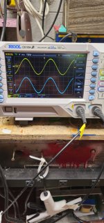
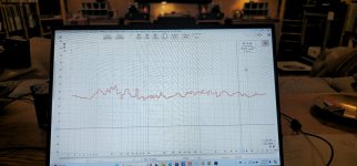
Nothing fruitful yet. I pulled the unit out and opened it. Hooked up to an amp with the inputs shorted and....nothing. Both channels were equally quiet. Hooking an oscilloscope up didn't show anything either. I now have the unit upside down and hooked up but the channels are almost identical at the moment regarding noise. Frustrating!
Pics of oscilloscope and RTA at each speaker. Clearly, one channel has much more noise than the other.


Pics of oscilloscope and RTA at each speaker. Clearly, one channel has much more noise than the other.


Do you mean it's upside down in the system it was originally noisy in?
. . . . and if so, does it become noisy again when you turn it right side up?
. . . . and if so, does it become noisy again when you turn it right side up?
Checking orientation is sound advice if You have MC SUT's inside - I have used some Hirata Tango for a while and they could be put anywhere but for Tribute's i had to find position far away from any psu transformer ( t-table, phono, amp ). Me thinks You tested that early on but check again the whole unit in situ.
- Home
- Amplifiers
- Tubes / Valves
- Phono-Stage Hiss