Recently I started to think about buying a turntable, so I need a phono stage for it. I'm playing with different active equalization topologies. I've found that finite open-loop gain (even with two high-μ tubes per stage with split equalization) leads to inaccurate RIAA curve reproduction. The error can vary from ±0.5dB for high-μ tubes to about ±2.5dB for low-μ tubes like ECC88. In other words I can't get perfect -20dB shelf for 318μS zero. What error value is considered tolerable?
Maybe you could boost the loopgain by using a pentode as the second stage. In any case, both channels will normally have roughly the same loopgain, so why your worry that errors due to finite loopgain may not track between left and right?
If you want the inaccuracy to be inaudible during blind testing, you need to keep it below about +/- 0.2 dB according to an old article by Lipshitz and Vanderkooy. I'm not sure whether they assumed equal errors for left and right or not. If you just want to ensure the inaccuracy is not annoying, +/- 0.5 dB should be fine.
If you want the inaccuracy to be inaudible during blind testing, you need to keep it below about +/- 0.2 dB according to an old article by Lipshitz and Vanderkooy. I'm not sure whether they assumed equal errors for left and right or not. If you just want to ensure the inaccuracy is not annoying, +/- 0.5 dB should be fine.
have you checked the error value of your hearing on both left and right ears? Serious question here - its highly likely your own hearing is more mismatched than the output of the pre-amp.
have you checked the error value of your hearing on both left and right ears? Serious question here - its highly likely your own hearing is more mismatched than the output of the pre-amp.
True, but you tend to compensate for the inaccuracies of your ears because you hear everything with those inaccuracies in place.
DF96 is on the money (as usual). Getting reasonably good channel-channel accuracy is key. No 5% parts would be the “obvious-man's” mantra, but just try to find vetted 1% capacitors that don't cost a fortune, or 1% matched amplification bulbs (or FETs).
In the end it becomes a project of “buy good stuff, test values of all, adjust formulæ, and try to ensure that your changes are to the resistor side of the parts list”. Even pretty high precision resistors are by far the cheapest-to-acquire part of the whole thing.
The notion of building a passive network is not bad, but it is vexed by almost-always failing to account for both the signal source impedance characteristics and the following preamplifier stage's impedance fu.
In the end, "magic canned solutions" that have been iterated to death are probably the best start-point for your design. Active, not passive. Measure, adjust, measure, adjust. Getting to channel-matching of 2% or 3% is awfully darn good. Good enough. remembering that 20log10( 1 + 2% ) = 0.17 dB …
I'd say ⅕ decibel is REALLY good matching.[br]GoatGuy
Last edited:
I think I can't guarantee it too. Maybe I should look to passive equalization instead.
I use passive exclusively. Sounds excellent when designed properly. As Goatguy said using well matched parts in both channels is key. I used 1 and 3 percent caps and trimmed them with pf values, same with 1 percent resistors. Considering the parts count it isn't expensive compared to the entire project and you're only building it once, right?
Last edited:
> active equalization
Well, pencil-check the requirements.
Say gain of 100 at 1KHz.
Need gain of 1,000 in deep bass.
For 1dB (10%) accuracy with perfect Rs and Cs, you need gain of 10,000.
The 0.2dB rule suggests open-loop gain above 50,000.
How can you do that?
12AX7 + 12AX7 = 50 * 50 = 2,500 which is way short.
12AX7 + 6AU6 = 50 * 200, 10,000 which is still not enough for "real good".
You can pencil 12AX7 + 12AX7 + 12AX7, 50*50*50, >100,000. But the phase does not work out for NI feedback. (Inverter is just hissy.) You can diff-pair the input for gain of 60,000, OK. But three high-cuts in the forward path begs for instability.
IF you can do flat-gain stages with perfect R-C between, then your residual gain error is a flat frequency term, which can be trimmed with a balance or two gain controls. Because the needles also have some sensitivity variance side to side, such a control may be needed anyway.
The final trick is to accept that the deep bass will vary with tube rolling and aging, and make that resistor trimmable for the specific tube in the socket. If the forward gain "2500" is really 2300 or 2600, so you have a bare 8dB NFB and the final gain won't track the ideal resistor value, trim the resistor so the bass gain is correct. (Re-trim after rolling or aging.)
Last edited:
Yep, teach tubes to do op-amp tricks is not as easy as it seems. Anyway, I have another question. How much Miller capacitance of high-u based gain stage affects frequency response of complete setup?
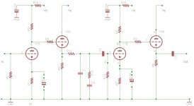
The best way for me to use phono tubes is like the Riaa comes from Klimo.
There is the first stage at gain follwed by a cathode follower ( in dc) -passive riaa-another gain stage and c.f. on the output.
In this way the attenuation of the eq. circuit is around 0,2-0,3 dB; you can use a low Z on riaa with benefit on s/n.
The Miller capacity is a value that must be considered and only with a practical test you can fins the right value od components of riaa to have a flat curves.
In attach the circuit I use; with ecc83 as gain and ecc88 for c.f.
Good results
Walter
Attachments
I think at least with ECC83 cathode resistors could be left unbypassed for gain stability and more linearity.
Not needed
In this configuration you can bypass or not the cathode without any changes on riaa equalization
Walter
In this configuration you can bypass or not the cathode without any changes on riaa equalization
Walter
Well, pencil-check the requirements. <snip>
Regarding the three-stage feedback amplifier, as the requirements on the open loop gain drop with frequency, you can allow a rather blunt type of frequency compensation. Maybe that helps.
Besides, it is not necessary to do everything with a single loop. I once designed a moving-magnet RIAA amplifier consisting of a triode-connected EF86 working as an open-loop common-cathode stage, a cathode follower and a two-stage feedback amplifier that did the equalization. It worked quite nicely: with 1 Mohm load the RIAA response error of both channels was between -0.191 dB and +0.123 dB from 20 Hz to 20 kHz with respect to 1 kHz (measured values, 1 % tolerance components, no trimming). With 10 kohm load there was some extra roll-off below 100 Hz, but the response did not drop below -0.3 dB at 20 Hz.
A disadvantage was the relatively large minimum input capacitance: about 90 pF due to the Miller effect in the triode-connected EF86. Most cartridges require a few hundred picofarads of load anyway, but it makes the amplifier unusable for cartridges that are designed for a low load capacitance.
Hi,
Once upon a time, long ago, I built a numerical optimization based software tool that solved for the best component values ("best" means tightest fit to the ideal RIAA equalization curve), NOT assuming ideal opamps. Instead, the amplifier had these non-idealities:I'm curious, in the world of vacuum tube based RIAA equalizers, are there other nonidealities that need to be considered? Or, is the above list necessary & sufficient to make a good quality vacuum tube MM preamp?
Thanks for your replies!
Once upon a time, long ago, I built a numerical optimization based software tool that solved for the best component values ("best" means tightest fit to the ideal RIAA equalization curve), NOT assuming ideal opamps. Instead, the amplifier had these non-idealities:
- Amplifier gain at DC is not infinity; instead it is a known, finite number (user supplied)
- Amplifier's unity gain bandwidth is not infinity; instead it is a known, finite number (user supplied)
- Amplifier's phase margin is less than 90 degrees; namely, there are more than one poles in the open loop transfer function. Phase margin and/or second pole position are user supplied
- Amplifier's open loop output impedance is greater than zero (user supplied)
Thanks for your replies!
RIAA accuracy is why a tube pre usually amplifies the cartridge flat ( 6AU6 ) then feeds a passive RIAA and then uses the second stage to boost the equalized signal.
I'm thinking of x75 low noise silicon head amp , RIAA , 6922 output EQ
I'm thinking of x75 low noise silicon head amp , RIAA , 6922 output EQ
Last edited:
see SY's article "His Master's Noise" -- one shouldn't assume that "rp" is constant for all triodes, it changes over time and varies from tube to tube.
His Master's Noise: A Thoroughly Modern Tube Phono Preamp
I have another question. How much Miller capacitance of high-u based gain stage affects frequency response of complete setup?
LOTS. Especially if you plan to use pretty much any modern MM cartridge. Don't forget stray capacitances, sockets, connectors, cables, etc.
MC cartridges just pose different problems to solve.
If you want to make a VERY nice and proper RIAA, I suggest looking to Allen Wright's designs for inspiration (RIP).
Ian
- Status
- Not open for further replies.
- Home
- Amplifiers
- Tubes / Valves
- Phono preamp RIAA curve accuracy