The purpose of this project was partly so that I can use my turntable with my stereo, but more as a learning experience. I wanted to put the transformer to use, plus I wanted to design & build my first linear power supply. I didn't want to copy your design/layout verbatim. I figured I'll learn more by building something first and then troubleshooting and making tweaks to improve the performance.Humm, While I'm trying not to be negative about it, you might have asked me why I used the particular PS configuration, ICs and arrangement I used. It would have been faster and simpler than posting on another site. One thing inaddition to all the above comments is that if you use a steel enclosure it will be even quieter. 🙂
Thanks so much for the resource by the way! I'm an EE student with an Associate in EET so I have a fair bit of physics/circuit analysis knowledge, but very I'm still rather inexperienced with physical layout and audio in general.
What's FWB?With a true FWB supply the ripple will be 120 Hz, so that's a useful clue.
Also, I've definitely ruled out power supply ripple. The hum is clearly at 60 Hz.
They are not. I will look into that. I also plan to move the ground closer to the input.Are your input cables screened? I can't see any screening. You need to ensure that the signal ground closely follows the signal. You seem to have it well apart. Coax is best; failing that, use twisted pair.
This was an issue of getting the right voltage from the transformer. I think if I used a bridge rectifier, I would have only gotten +/- 8v, or possibly 7 with good regulation.You would have been better to use a full-wave rectifier, rather than a pair of half-waves.
Ok well that's encouraging I guess! HahaPrecise details of PSU grounding matter. There are lots of ways to get this wrong, and only a few ways to get it right. Hence thermodynamics guarantees that most people get it wrong at first.
By the way thanks a lot for the help everyone! My school load is pretty insane over the next month and a half so sorry if I'm slow to implement your suggestions!
Last edited:
FWB is "full wave bridge". One is usually best off to use a center tapped transformer for a dual polarity supply, but naturally the right one is never in the junk box. Still, I think the major problem here is proximity to the transformer. Get that moved away and then troubleshooting the remaining problems will be much easier.
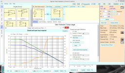
Predicting 12dB SNR (noise + hum) using 2_D magnetic model
I built an opamp preamp based on a schematic I found online (designed my own linear power supply) and I'm getting a lot of noise. Assuming full output is line level (haven't measured that but that's the idea), then the S/N ratio is only about 40dB the way I measured it. There are definitely quiet parts of some records when the noise is louder than the signal.
MitchMev: attached are 3 screen shots of a tool that explain your "noise"/hum.
Attach#1 shows the EMI database: I added a new interferer at the bottom, intending its 2 Amps to represent the peak 60Hz currents thru the 2 yellow wires from XFORMER to the 2 half-wave diodes. Your opamps probably only use 20mA, so the 2Amps peak may be a bit too high. BTW, this 2Amps is our aggressor energy.
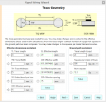
Attach#3 is the physical description worksheet for the circuit loop that is vulnerable to magnetic field. The 25mm length is about what I see on the bottom left, from RCA jacks to the wiring-board. The 15mm height is my estimate of distance between the GND wire and RCA jack center post.
Attach#2 shows the SCE (Signal Chain Explorer) topology I set up; its just a 1milliVoltPP sensor, a "TRC" which is the 25mm * 15mm input loop, and an opamp with RIAA feedback. You'll notice the frequency response in lower part of the attachment. On the right side, at top, is the SNR of 16dB.
Looking below that, you'll notice the Aggressor is 1.13 milliVolts while the thermal noise is only 49 microVolts.
Cure? Twist those two yellow wires together tightly; their currents are in opposing direction, thus their magnetic fluxes ideally will perfectly cancel if an ideal twisted pair (machine twisted for uniform twists) is used. Or place a piece of steel between the top and bottom of the circuits.
By the way, you can download this tool, SCE, for free from robustcircuitdesign.com; it needs .NET so that also will be downloaded if your Windows7/8/10 computer does not already have .NET.
And..............where is the transformer? I don't see it.
Best wishes
tankcircuitnoise
Attachments

Last edited:
tankcircuitnoise, that's great thank you!
The transformer is mounted on the outside if the enclosure. The bulk of the hum originally was from magnetic fields being picked up by my receiver preamp (poorly shielded, if at all). The hum is still noticeable but definitely tolerable for my own use. I am planning on building another unit with my friend for his system, so I will take care to implement these suggestions.
The transformer is mounted on the outside if the enclosure. The bulk of the hum originally was from magnetic fields being picked up by my receiver preamp (poorly shielded, if at all). The hum is still noticeable but definitely tolerable for my own use. I am planning on building another unit with my friend for his system, so I will take care to implement these suggestions.
- Status
- Not open for further replies.