I built an opamp preamp based on a schematic I found online (designed my own linear power supply) and I'm getting a lot of noise. Assuming full output is line level (haven't measured that but that's the idea), then the S/N ratio is only about 40dB the way I measured it. There are definitely quiet parts of some records when the noise is louder than the signal.
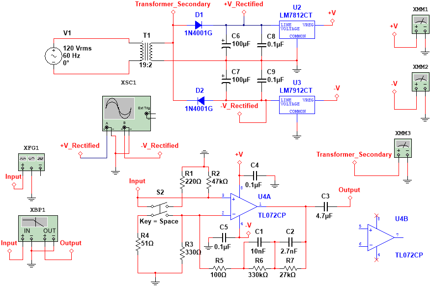
Here's the schematic I drew up:
It seems to be a grounding issue, since the noise goes away when the input is disconnected. Here's a picture of the construction:
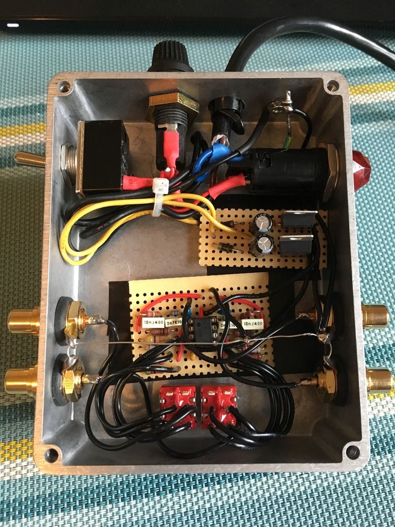
I actually just realized that I have the grounds mostly connected near the output (right side) even though I intended to connect them to the input. Could this be a factor? Or not so much?
Edit: I should add that I was measuring the noise at 60 Hz, not 120. So I think it's safe to rule out power supply ripple issues.
I'll also add that the designer of the op-amp topology (located here: http://diyaudioprojects.com/Chip/Opamp-Phono-Preamp/) listed his signal to noise ratio as in the range of -90 to -100 dBV for different frequencies.
Here's the schematic I drew up:

It seems to be a grounding issue, since the noise goes away when the input is disconnected. Here's a picture of the construction:

I actually just realized that I have the grounds mostly connected near the output (right side) even though I intended to connect them to the input. Could this be a factor? Or not so much?
Edit: I should add that I was measuring the noise at 60 Hz, not 120. So I think it's safe to rule out power supply ripple issues.
I'll also add that the designer of the op-amp topology (located here: http://diyaudioprojects.com/Chip/Opamp-Phono-Preamp/) listed his signal to noise ratio as in the range of -90 to -100 dBV for different frequencies.
Last edited:
> measuring the noise at 60 Hz, not 120
"Noise" can be hiss, hum, or buzz. Which is it? How are you measuring "at 60 Hz"?
> schematic I drew up:
Won't open; or it is a thumbnail the size of a bat's thumb.
What I see is AC wiring inside the phono box, looped for extra radiation. Undersize first filter caps. No "optional" caps on regulator outputs.
> the designer ... listed his signal to noise ratio
In principle we can make a phono preamp with NO hum. (Batteries out in the woods.) We can not make a preamp with NO hiss, hiss is universal. His design will give hiss on MM needles considerably below surface noise. Even on MC gain it won't be "louder than soft passages".
Disconnect the AC and wire two 9V batteries. Does that hum?
Not sure what the technical difference is between those three things, but it looks like a 60 Hz sine wave on the scope and the DMM reads 60 Hz."Noise" can be hiss, hum, or buzz. Which is it? How are you measuring "at 60 Hz"?
See if this link works: RIAA Preamp_zps2uao099l.png Photo by Mitch_Meverden | PhotobucketWon't open; or it is a thumbnail the size of a bat's thumb.
There are additional caps at the Vcc+ and Vcc- pins on the op amp. And what size caps would you recommend for this purpose? 470uF? 1000uF? I can go in and shorten my AC wires. I left a lot of extra wiring to make it easier to go in and make changes.What I see is AC wiring inside the phono box, looped for extra radiation. Undersize first filter caps. No "optional" caps on regulator outputs.
I'll try this when I get a chance. Will try shortening the AC wires in the meantime.Disconnect the AC and wire two 9V batteries. Does that hum?
The TL072 is an extremely noisy op-amp for RIAA duties, something like the 2132 or 5532 should be substantially quieter. Fix the other problems first.
Your grounding looks messed up. Run separate ground wires from input and output to a single common ground point, ground to chassis at this point.
Make sure all RCA jacks are actually isolated from the chassis box before connecting the ground wiring to them.
Shorten up AC wiring as much as possible, where is the power transformer located?
I can't see where the transformer center tap is grounded, but it should go directly to the ground side of the filter caps, from there to the regulators and output cap grounds, and finally to the common ground referenced above.
Note that if other things in the system are also grounded a ground lift network between the "mecca" ground (all of the connections I have referenced above) may be required to avoid a ground loop. This comprises a 4.7 - 10 ohm 1W resistor in parallel with an anti-parallel pair of silicon diodes like 1N5408 or similar.
Duh, I just realized you are using half wave rectification; you need much BIGGER input caps.. I bet a big part of the problem is ripple blasting through those regulators. Replace with 1000uF or greater, and use an output cap.
I have a 5532 I could swap in easily.The TL072 is an extremely noisy op-amp for RIAA duties, something like the 2132 or 5532 should be substantially quieter. Fix the other problems first.
Should this be at the earth ground point or just somewhere near the input/output? Also should the power supply be chassis grounded separately from the earth ground and the input/output chassis ground?Your grounding looks messed up. Run separate ground wires from input and output to a single common ground point, ground to chassis at this point.
I isolated them from the chassis with rubber grommets.Make sure all RCA jacks are actually isolated from the chassis box before connecting the ground wiring to them.
It is mounted on the outside of the enclosure.Shorten up AC wiring as much as possible, where is the power transformer located?
I've also been considering separating earth from common with a cap and resistor in parallel. Does this accomplish relatively the same thing?Note that if other things in the system are also grounded a ground lift network between the "mecca" ground (all of the connections I have referenced above) may be required to avoid a ground loop. This comprises a 4.7 - 10 ohm 1W resistor in parallel with an anti-parallel pair of silicon diodes like 1N5408 or similar.
By output cap, do you mean on the regulator outputs? Or actually on the audio output?Duh, I just realized you are using half wave rectification; you need much BIGGER input caps.. I bet a big part of the problem is ripple blasting through those regulators. Replace with 1000uF or greater, and use an output cap.
Last edited:
You cannot look at it that way as the two half wave current loops are entirely independent of each other, from the transformer standpoint that is true, from the load standpoint it's not.
To clarify when I mentioned output caps I was talking about regulators.
Since each regulator is fed by a half wave rectified DC it is likely that the ripple rejection of the regulators is insufficient to keep it entirely off the output. The PSRR of most op-amps is pretty good at 60Hz, but the waveform has high frequency components that will capacitively couple to nearby circuitry even if the op-amp can reject the ripple on its supply pins.
The grounds should all return to one common "mecca" ground point, this point can float on the previously described diode/resistor ground lift. They should be completely separate in my experience.
WRT the ground lift in the event that the power transformer develops a primary to secondary short omitting the diodes means it is likely that everything except the case becomes energized when the resistor goes up in smoke - dangerous. The diodes need to support sufficient current to give the fuse time to blow.
The 5532 should be significantly quieter than the TL072.
Power supply ripple is on the order of microvolts. Undetectable on the scope at 5mV/div.
I tucked the AC wires underneath the power switch, slightly further away from the audio circuitry and am now getting a S/N ratio of about 60. Will try cutting them shorter when I have some free time this week. I also might be able to fit the power supply board behind the lamp to get it further away from the audio board, though it will be a tight fit. Will also work on the ground issues.
Edit: Also, I just dropped in a 5532 and the noise was actually significantly worse. Not sure why that might be...
Last edited:
Progress! Likely the increase in noise is due to the current noise of the 5532, I had not considered the effect that might have with the moderately high RIAA network component values. I would try to get a 2132 or 2134 to try, these are FET types and will have lower current noise than the 5532..
I suspect the ripple is > uV, but I have no trouble believing you can't see it with the scope.
I suspect the ripple is > uV, but I have no trouble believing you can't see it with the scope.
I don't mean the ripple is 1 uV, but it's definitely less than 1 mV. I'll see what I can measure with the DMM.
And while I think better op-amps will help, they certainly won't solve the problem, as it seems pretty clear that mutual induction is a major source of the noise. Would it make sense that this would go away entirely when the input is disconnected? I suppose it's sort of an open circuit.
Also, I'll report back when I've made some more changes, it might be a while though, I'm pretty busy with school work.
Here's a new development: When I move the preamp away from the receiver the noise decreases significantly, to a point. It doesn't seem to keep getting quieter the further I move it. I have a feeling the RCA cables from the turntable are picking up the magnetic field from the transformer (mounted on the outside of the unit) as well.
I'll investigate this further when I get the chance. I'll also try to keep taking noise measurements along the way.
I'll investigate this further when I get the chance. I'll also try to keep taking noise measurements along the way.
Last edited:
Any ideas for fixing that?Magnetic coupling like that really smells like a ground loop issue.
For audio, usually when you say noise you're talking about hiss, not low frequency stuff. That's usually hum, rumble or motorboating, depending on the circumstances.
It sounds like you've got hum. FWIW, when I build an RIAA preamp, I build it in a 17" wide box (to accept a rack panel front) and put the transformer and AC connections far to one side. The RIAA section goes all the way to the other side, and if there's a line section, it goes in the middle. The isolated input strips also go to the side with the RIAA board, with the output in the middle.
IMO, the only way you can get a hum free RIAA amp in that size box is to put the power supply outside and far away, or use a wall wart. Even mu-metal probably won't fix this.
No AC wiring loop can have any part in common with DC loops. A single point ground is needed, but I usually establish that using some lugs nearer the boards than the supply. In addition, any local PS bypass capacitors need to return to the single point ground, not to the signal grounds.
Done properly, any hum should be below the level of the high frequency noise, or at least inaudible under any listening condition.
Thanks Conrad,
Yeah it's definitely hum (60 Hz plus some harmonics), sorry for using some bad terminology.
I have the hum reduced to a level I'm content with (still noticeable), but I built this with the full understanding that I would want to go back in and tweak stuff.
I currently have earth connected to chassis right near the power cable entry hole, then I have that point connected to a star ground at the output jacks (I had intended to make this star at the input jacks but looked at it backwards). Are you saying I should connect the PS and signal grounds to chassis at a point closer to the amplifier board?
One thing I've been wondering is if there is a problematic ground loop in my RCA cable runs, since the two channels are potentially grounded together at both ends. Is this something worth looking into? Or do I assume that the right and left "grounds" are floating at the turntable and need to be connected together at the preamp input for both signal loops to be closed?
Humm, While I'm trying not to be negative about it, you might have asked me why I used the particular PS configuration, ICs and arrangement I used. It would have been faster and simpler than posting on another site. One thing inaddition to all the above comments is that if you use a steel enclosure it will be even quieter. 🙂
One problem with the proximity induced magnetic hum is you'll have a heck of a time figuring out what other ground problems may or may not be present. With a true FWB supply the ripple will be 120 Hz, so that's a useful clue. I don't like the term ground loop because it's too vague and not all ground loops cause problems.
Steel has its benefits, but even with a fairly well equipped shop, I hate the stuff for chassis. Sometimes I'll install a steel shield or internal enclosure if needed. To fight magnetic problems you need the steel to fully enclose or at least form a shorted turn around the problem.
Steel has its benefits, but even with a fairly well equipped shop, I hate the stuff for chassis. Sometimes I'll install a steel shield or internal enclosure if needed. To fight magnetic problems you need the steel to fully enclose or at least form a shorted turn around the problem.
Are your input cables screened? I can't see any screening. You need to ensure that the signal ground closely follows the signal. You seem to have it well apart. Coax is best; failing that, use twisted pair.
PSU cables need to be twisted so as far as possible every wire carrying AC current is paired with another wire carrying exactly the same current in the opposite direction. Keep AC wiring as far as possible away from the audio circuit, especially the input and feedback point.
You would have been better to use a full-wave rectifier, rather than a pair of half-waves.
Precise details of PSU grounding matter. There are lots of ways to get this wrong, and only a few ways to get it right. Hence thermodynamics guarantees that most people get it wrong at first.
Last edited:
- Status
- Not open for further replies.
- Home
- Source & Line
- Analogue Source
- Phono Preamp Bad S/N Ratio