By the way, you can make an exact anti-RIAA network in LTSpice with the Laplace statement in an arbitrary voltage source. With an RC circuit, the response doesn't keep increasing to infinity, as it should according to the RIAA standard.
Yes, for simulations you can do that. A real pre-emphasis network always has a gain limit,
though it can be extended by increasing the midband attenuation.
though it can be extended by increasing the midband attenuation.
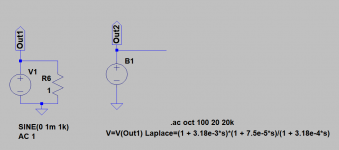
Here is the RIAA source that I use for simulation. The "n" parameter normalizes the 1 KHz PHONO output level to match the sine wave amplitude voltage of the SIGNAL source. In other words, if the SINE value is 1 mV at 1 KHz as shown, the PHONO output at 1 KHz will also be 1 mV (peak).
Attachments
Here is the RIAA source that I use for simulation. The "n" parameter normalizes the 1 KHz PHONO output level to match the sine wave amplitude voltage of the SIGNAL source. In other words, if the SINE value is 1 mV at 1 KHz as shown, the PHONO output at 1 KHz will also be 1 mV (peak).
That's neat as you can change the parameters on the fly if you have a bunch of old, old records!
Tape Head Inverse Sources
Thanks. I've found this model to be very useful.
For those who design tape head preamps, I've also developed inverse sources for the most common NAB and IEC equalizations. I've attached that file here. As with the RIAA source, each model has a parameter which normalizes the 1 KHz output to match whatever level is specified for its respective signal source.
Note that the IEC specifications are defined by only one (1) time constant so they are effectively just simple first order filters.
Attachments
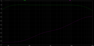
On further investigation some of the hf rolloff is due to the inverse RIAA circuit so I will add the calculated source later and rerun it. See the attached output graph and you will see the input start to flatten out around 20 or 30k.

P.S. it looks like the output can drive at least 5000pf without significant loss of hf response. Would that be adequate for typical interconnect cables to the line amp?
P.S. it looks like the output can drive at least 5000pf without significant loss of hf response. Would that be adequate for typical interconnect cables to the line amp?
Attachments
Seeing as these interconnects are 90pf, I'd say so.
Premium Grade Low Capacitance RCA Audio Cable (3 Feet) | Fluance
Premium Grade Low Capacitance RCA Audio Cable (3 Feet) | Fluance
On further investigation some of the hf rolloff is due to the inverse RIAA circuit so I will add the calculated source later and rerun it. See the attached output graph and you will see the input start to flatten out around 20 or 30k.
One characteristic of physical inverse RIAA filters is that they unavoidably have an extra high frequency time constant that is not part of the RIAA standard. This usually takes effect at a high enough frequency as to not interfere with the response up to 20 KHz or so. Here is a good article describing RIAA circuit design using active (feedback) equalization, and the same feedback filter can be used as an inverse RIAA filter.
Phono Preamp Design Using Active RIAA Equalization
The model that I provided in post #24 is a mathematically precise representation of the inverse RIAA curve so it will not introduce any simulation errors as far as the input signal is concerned.
P.S. it looks like the output can drive at least 5000pf without significant loss of hf response. Would that be adequate for typical interconnect cables to the line amp?
It can probably also drive that without excessive distortion, when you take into account the roll-off of high frequencies in normal music.
Cheap cables with PVC dielectric can have a capacitance as high as 280 pF/m, but even then you can drive 17.85 m (58 feet 7 inches) of cable with an output that can handle 5 nF. Should be more than adequate, even when the line amp has an RF filter with a capacitance of a few hundreds of pF at its input.
For those who design tape head preamps, I've also developed inverse sources for the most common NAB and IEC equalizations. I've attached that file here. As with the RIAA source, each model has a parameter which normalizes the 1 KHz output to match whatever level is specified for its respective signal source.
Note that the IEC specifications are defined by only one (1) time constant so they are effectively just simple first order filters.
Thanks! By sheer coincidence, some five hours before you posted this, a friend of mine called me and asked me to redesign a tape head preamplifier. He'd never done that before, nor anyone else.
Last edited:
Here is the RIAA source that I use for simulation. The "n" parameter normalizes the 1 KHz PHONO output level to match the sine wave amplitude voltage of the SIGNAL source. In other words, if the SINE value is 1 mV at 1 KHz as shown, the PHONO output at 1 KHz will also be 1 mV (peak).
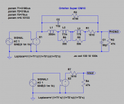
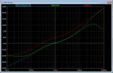
I think that this is Hans' model for an Ortofon Cartridge, compared to a simple resistive model:
Attachments
You get lowest loss and lowest capacitance with cables using foam polyethylene dielectric, many believe that teflon dielectric is the best but polyethylene is actually better, lower loss and lower dielectric constant, the only downside is that maximum operating temperature is 90 C.Cheap cables with PVC dielectric can have a capacitance as high as 280 pF/m
Even better is polystyren but it is difficult to make soft, it is usually brittle but its has even lower losses than polyethylene.
- Home
- Amplifiers
- Tubes / Valves
- Phono Calculations