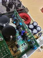
Im working on this amp for a friend. No power light. No voltage to chip that oscillates the 12v to transformer. I need a schematic.
Anybody have a schematic?
John
Anybody have a schematic?
John
There aren't many PG diagrams available. The circuit may be similar to one of their other amps like the following one:
https://elektrotanya.com/showresult?what=phoenix gold ms2125&kategoria=&kat2=all
If you don't get what you need here, try the Phoenix Phorum. They aren't likely to give you the diagram but they will have someone who will have the diagram and will be able to answer questions definitively.
If you want to continue here, post the DC voltage on all terminals of the SB3525. Copy and paste the following list and fill in the blanks. Since the forum now deletes blank spaces, you'll need to add one between the colon and the numbers you enter.
Pin 1:
Pin 2:
Pin 3:
Pin 4:
Pin 5:
Pin 6:
Pin 7:
Pin 8:
Pin 9:
Pin 10:
Pin 11:
Pin 12:
Pin 13:
Pin 14:
Pin 15:
Pin 16:
Hi Perry,
I had already down loaded that print. It somewhat helped, but not really. I have no power to the IC's on that little board (Vcc and GND). None of the leds are on also (green, red, yellow).
I have not tried the Phoenix forum yet. Thanks...
The small board has 20 pins. I put a interconnector on that board to insert and pull out easily.
Attachments
Hi Perry,
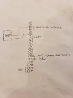
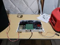
I attached a pic with voltages.
The Vcc for the IC's on the small board goes to pin 3 and 4. Their grounds are pins 19,20.
The remote start voltage is pin 15, with a perfect 12v.
I did try to reverse engineer the Vcc voltage and found it goes to a 4N35 ic on the big main board (i marked it 4n38 on drawing); an optocoupler.
I cannot find any opens or shorts on any components.
Attachments
I think you should have 12v on pins 1 and 2 from the notes I have.
Is the fuse for the amp blown?
Is the fuse for the amp blown?
Hi Perry,
Pin 1 and 2 have continuity to the trace. I pulled the cap and I do not have continuity to trace where the cap is soldered.
Damaged trace.
Looks like either cap leakage or moisture. Probably cap leakage.
I'm gonna order some caps and replace them.
I will update this thread when I get them replaced.
Thanks again Perry!
Attachments
You may want to pull (at least) one of each different size/series cap to see if any others have leaked.
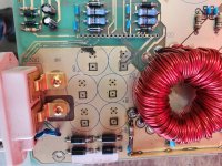
After cleaning the board thoroughly with acetone, take a bright light and aim it at the back of the board for any solder pads that had electrolyte leak on them. If you have any that look like the attached image, electrolyte may have saturated the fiberglass and it may have to be cut/dug out.
After cleaning the board thoroughly with acetone, take a bright light and aim it at the back of the board for any solder pads that had electrolyte leak on them. If you have any that look like the attached image, electrolyte may have saturated the fiberglass and it may have to be cut/dug out.
Attachments


If they're not leaking, they're likely OK. Some amps had a LOT of cap failures and for those, a full recap is required. I know that these (and many other PG amps) had bad primary filter caps. The rest, I don't know. I had an M100 come in before that had extensive board damage that resulted in a large part of the board burning.
I suggested checking the various caps of each type to see if they were leaking. Looking at the photo, there aren't many caps so it wouldn't be hard to replace the electrolytics.
Did the board show signs of electrolyte saturation around the solder pads?
Did you repair the trace (temporarily or permanently) to see if the amp would power up?
Hi Perry,
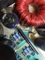
I'm going to replace the 6 primary caps and the two big ones.
The only ones leaking were the 6 primary ones.
C57 did show signs of electrolyte saturation around solder pads.
I soldered temp wired a jumper wire and it did power up.
I am going to repair the trace on pin 15 for remote power up. I did notice that corrosion initially, but I had continuity.
John
Attachments
Hi Perry,
I'm almost there. I did a check on the bass and gain pots and the "bass " pot will not change resistance.
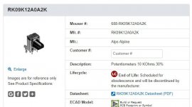
I did some research and it is a 10k pot. It is a very different pot then what I am familiar with.
It has extra leads on it. I did take the pot apart and found the knob stem was broken. I could just replace the knob from another.
I think this one from mouser will work.
John
I'm almost there. I did a check on the bass and gain pots and the "bass " pot will not change resistance.
I did some research and it is a 10k pot. It is a very different pot then what I am familiar with.
It has extra leads on it. I did take the pot apart and found the knob stem was broken. I could just replace the knob from another.
I think this one from mouser will work.
John
Attachments
Where are the extra leads?
It would be random luck if the shaft from one manufacturer would work with the internals of another manufacturer but it's possible.
It would be random luck if the shaft from one manufacturer would work with the internals of another manufacturer but it's possible.
Hi Perry,
I did find a correct pot for the bass gain (Alps 10K ohm 9mm Dual Rotary Potentiometer Pot RK09K12A0A5F Variable Resistor) on ebay.
The amp is working now. I do have to clean some of the other pots and push buttons as they are a little scratchy and flakey. Let me know what you normally do for these scratchy pots. i have Deoxit contact cleaner I normally use.
Thanks again for all your help. I would of not gotton this going without your help!
John
www.pinballmemories.com
Attachments
Use whatever contact cleaner you generally use that leaves a lubricant behind.
I'd have to see what the pots look like to offer any more specific advice.
I'd have to see what the pots look like to offer any more specific advice.
Hi Perry,
Ok, everything is working correctly now. I have one last question:
The fan does not run. It is not very hot. I have let it on playing to see if the fan comes on.
Does the fan only come on when unit is hot?
John
Ok, everything is working correctly now. I have one last question:
The fan does not run. It is not very hot. I have let it on playing to see if the fan comes on.
Does the fan only come on when unit is hot?
John
I don't know on this amp. Have you tried to find an owner's manual to see if that tells you about the fan?
- Home
- General Interest
- Car Audio
- Phoenix Gold ZX500 - dead, no power light.