Does anyone have links to a design guide for the SPP (Series Push Pull) configuration used by Philips for their old OTL amps ? EL86 Amps
My intent is a headphone amp specifically for 600 Ohm drivers. The combination of high resistance with low power requirements (about 1W) would seem to greatly simplify the classic issues with OTL designs for normal speaker loads and higher power.
I want to re-spec the components in the Philips SPP design for lower voltage and larger tubes (triode strapped 6L6?)
Does anyone have links to a design guide for the SPP (Series Push Pull) configuration
used by Philips for their old OTL amps ?
There are also some references at the end.
The SPP Amplifier | audioXpress
Last edited:
The short answer is no, I am not certain that I need that much power (and cannot imagine that I would). However the infallible internet is full of links claiming that I do.
How important is the power rating with headphone amps? | Headphone Reviews and Discussion - Head-Fi.org
How much current do headphones typically draw from an audio source? - Quora
But with a 600 ohm load should I study the SPP approach, or just accept the consequences of a low load?
The 2A3 predicts wretched harmonic distortion (both 2nd and 3rd) on page 3 of the links below:
https://frank.pocnet.net/sheets/127/2/2A3.pdf
The 6L6 does not look as bad as it predicts about 7% 2nd harmonic and 0 3rd and 4th on page 5 of the following:
https://frank.pocnet.net/sheets/127/6/6L6G.pdf
But if the 6L6 is triode-strapped will the distortion curves look more like the 2A3 and other power triodes?
This is not a new problem.
Putting 1 Watt in 600 Ohms is a Line Amplifier, for broadcast or telephony work.
If there was a "cheap" way to do it WELL, it would be universal. Instead we "always" use a transformer.
Why? Vacuum is very thin. Does not conduct well. Conducts different depending how many electrons are flowing. The numbers for a "fat" tube are like 1,000 Ohms internal resistance. So at 600r you are already losing 62% of power in the tube, not the load. Further if you load a tube this hard it WILL be "bent", high 2nd harmonic. And a real key point is: how can you separate the audio from the DC? Resistance-coupling "works" for very low powers. The maximum efficiency of resistance-coupling is about 8%, and you can't get there with tubes, so you are looking at over 20 Watts of tube and resistor to get 1 Watt out, and that with high THD.
When broadcast designers wanted +30dBm (1W) with low THD, they used push-pull transformer, and often a pair of 6V6-class tubes (8W high THD but cleaner at 1W/+30dBm). The cheap option was P-P transformer with a large twin-triode for most of a Watt.
The Philips speaker amplifiers were cheap and significant THD. They were good table radios, not Hi-Fi.
如何实现高保真耳机放大器的设计(二) - 放大器 - 电子工程世界网
http://www.eeworld.com.cn/mndz/2013/1105/article_20241.html
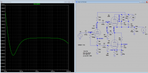
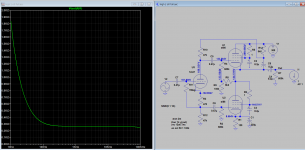
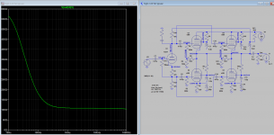
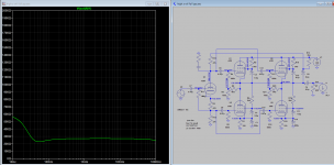
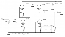
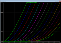
This article may answer to the question of triode mode for SPP amp as headphone amp applications, you may be interested also I attached a few SIM of SPPP pentode and triode mode the output Z for comparison. It appears you can drive a 200 ohms HP with SPPP pentode mode, anyone heard how it sounds? You can add front end stage with Gnfb to further drive down distortion. With bootstrap of upper tube this amp perform a bit better than the origin EL86 SPP. The full amp resemble Futterman Pentode OTL, however.
Other resources:
The SPP Amplifier | audioXpress
Unbenanntes Dokument
Construa o seu amplificadoe
http://6bm8.lab.free.fr/Documentations/BackuPTubes/SRPP de A à Z/view.php.htm
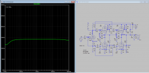
BTW the poor bottom end response is due to fallen output Z and so the output cap value after adjusted, all straight up to 10Hz.
http://www.eeworld.com.cn/mndz/2013/1105/article_20241.html
This article may answer to the question of triode mode for SPP amp as headphone amp applications, you may be interested also I attached a few SIM of SPPP pentode and triode mode the output Z for comparison. It appears you can drive a 200 ohms HP with SPPP pentode mode, anyone heard how it sounds? You can add front end stage with Gnfb to further drive down distortion. With bootstrap of upper tube this amp perform a bit better than the origin EL86 SPP. The full amp resemble Futterman Pentode OTL, however.
Other resources:
The SPP Amplifier | audioXpress
Unbenanntes Dokument
Construa o seu amplificadoe
http://6bm8.lab.free.fr/Documentations/BackuPTubes/SRPP de A à Z/view.php.htm
BTW the poor bottom end response is due to fallen output Z and so the output cap value after adjusted, all straight up to 10Hz.
Attachments
-
How to realize the design of high fidelity headphone amplifier (1).pdf291.5 KB · Views: 90
-
How to realize the design of high fidelity headphone amplifier (2).pdf311 KB · Views: 128
-
 SEPP pentode output Z.png93.5 KB · Views: 341
 -
 SEPP triode output Z.png91.1 KB · Views: 356
 -
 SEPPP triode output Z.png82.7 KB · Views: 338
 -
 SEPPP pentode output Z.png87.6 KB · Views: 341
Thanks for the information and references.
You mention that the the output cap was adjusted to address the bottom end response, but the schematics look the same. Do you know what change was made in the cap?
I have found handbooks and web tutorials which lead me through the selection of load lines and components for resistance coupled, cathode followers, and other standard configurations, but have found nothing for SPP. Can anyone steer me to references that walk me through the selection of the resistors and caps?
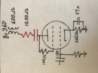
Can I just self-bias the 6L6 almost conventionally if I add a 1200 Ohm resistor to the 600 Ohm speaker load? (with a cap to block DC)
I see this done with guitar amps all the time so that they can be cranked without excessive volume, but never for hi-fi (probably for good reason). In any case I do not mind wasting energy as I can design for 3W so that I can use 1W.
A total load of 2000 Ohms puts the harmonic distortion where I want it (heavy on 2nd and light on 3rd)
Attachments
I have some 1950's european tube radio useing srpp mode for speaker output,especially Philips tube radio such as...BD753A...B5X62A...B5X92A...,etc. Philips radio use a very simple srpp circuit as previous discussion for operating in OTL mode, nearly 3~6w output power into 600~1000 ohm speaker with another tweeter speaker. Frequency response is flat but bass control effect seems a little bit weak,due to bass control need a lot of current supply that exceed otl tube plate current can afford . Through capacitor connect to 600 ohm headphone directly, if in medium output power level it still can get a wide frequency response with bass and treble control effect. Its my experence for reference,thanks ..
RC time constant - Wikipedia
Cutoff frequency:
fc in Hz = 159155 / τ in µs
τ in µs = 159155 / fc in Hz
So if coupling cap is 100u and load is 50 ohm, using short equation:
τ in µs=100*50=5000
fc in Hz= 159155/5000=~30
If coupling cap is 8.2u then
τ in µs=8.2*50=410
fc in Hz= 159155/410=~388
Assume that output Z is lower than the load, or you will get error, it is necessary to know Zout first whenever possible.
Last edited:
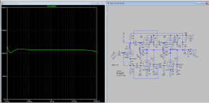
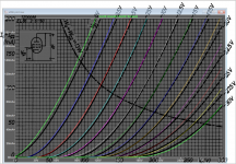
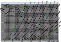
Here is the output Z of SEPPP triode mode after output cap C4 is adjusted from 8.2u to 100u so you can see the diff. The 2nd snapshot show the effect of screen current, Zout decreased as tube current increased
Attachments
Last edited:
Where did you get these EL86 models for LTSpice from?
Best regards!
I model mine, but found a close one here:
800 Ohm OTL versterkers van Philips. - Pagina 10 - Buizenradioclub
Code:
*
* Generic pentode model: 6CW5 / EL86
* Copyright 2003--2008 by Ayumi Nakabayashi, All rights reserved.
* Version 3.10, Generated on Sat Mar 8 22:39:44 2008
* Plate
* | Screen Grid
* | | Control Grid
* | | | Cathode
* | | | |
.SUBCKT EL86 A G2 G1 K
BGG GG 0 V=V(G1,K)+0.38874904
BM1 M1 0 V=(0.09419804*(URAMP(V(G2,K))+1e-10))**-1.560546
BM2 M2 0 V=(0.49010862*(URAMP(V(GG)+URAMP(V(G2,K))/5.4129723)))**3.060546
BP P 0 V=0.0055371733*(URAMP(V(GG)+URAMP(V(G2,K))/11.044434))**1.5
BIK IK 0 V=U(V(GG))*V(P)+(1-U(V(GG)))*0.0058898823*V(M1)*V(M2)
BIG IG 0 V=0.0027685867*URAMP(V(G1,K))**1.5*(URAMP(V(G1,K))/(URAMP(V(A,K))+URAMP(V(G1,K)))*1.2+0.4)
BIK2 IK2 0 V=V(IK,IG)*(1-0.4*(EXP(-URAMP(V(A,K))/URAMP(V(G2,K))*15)-EXP(-15)))
BIG2T IG2T 0 V=V(IK2)*(0.945717092*(1-URAMP(V(A,K))/(URAMP(V(A,K))+10))**1.5+0.054282908)
BIK3 IK3 0 V=V(IK2)*(URAMP(V(A,K))+2245)/(URAMP(V(G2,K))+2245)
BIK4 IK4 0 V=V(IK3)-URAMP(V(IK3)-(0.0035373923*(URAMP(V(A,K))+URAMP(URAMP(V(G2,K))-URAMP(V(A,K))))**1.5))
BIP IP 0 V=URAMP(V(IK4,IG2T)-URAMP(V(IK4,IG2T)-(0.0035373923*URAMP(V(A,K))**1.5)))
BIAK A K I=V(IP)+1e-10*V(A,K)
BIG2 G2 K I=URAMP(V(IK4,IP))
BIGK G1 K I=V(IG)
* CAPS
CGA G1 A 0.6p
CGK G1 K 6.9p
C12 G1 G2 4.6p
CAK A K 5.4p
.ENDS
Here is mine:
Code:
**** EL86P ******************************************
* Created on 12/07/2018 04:40 using paint_kip.jar
* [url=http://www.dmitrynizh.com/tubeparams_image.htm]Model Paint Tools: Trace Tube Parameters over Plate Curves, Interactively[/url]
* Plate Curves image file: el86p.png
* Data source link: <plate curves URL>
*----------------------------------------------------------------------------------
.SUBCKT EL86P P G2 G K ; LTSpice tetrode.asy pinout
* .SUBCKT EL86P P G K G2 ; Koren Pentode Pspice pinout
+ PARAMS: MU=10.74 KG1=462.84 KP=33.51 KVB=132.38 VCT=0 EX=1.357 KG2=4017.27 KNEE=12.86 KVC=2.498
+ KLAM=3.816E-9 KLAMG=3.967E-4   KNK=-0.044 KNG=0.006 KNPL=50 KNSL=11 KNPR=120 KNSR=29
+ CCG=3P CGP=1.4P CCP=1.9P RGI=2000.0
* Vp_MAX=400 Ip_MAX=350 Vg_step=2.5 Vg_start=0 Vg_count=13
* X_MIN=89 Y_MIN=52 X_SIZE=847 Y_SIZE=738 FSZ_X=1550 FSZ_Y=878 XYGrid=false
* Rp=1400 Vg_ac=20 P_max=12 Vg_qui=-15 Vp_qui=300
* showLoadLine=n showIp=y isDHP=n isPP=n isAsymPP=n isUL=n showDissipLimit=y
* showIg1=n isInputSnapped=y addLocalNFB=n
* XYProjections=n harmonicPlot=y dissipPlot=n
* UL=0.43 EG2=200 gridLevel2=n addKink=y isTanhKnee=n advSigmoid=n
*----------------------------------------------------------------------------------
RE1  7 0  1G    ; DUMMY SO NODE 7 HAS 2 CONNECTIONS
E1   7 0  VALUE=  ; E1 BREAKS UP LONG EQUATION FOR G1.
+{V(G2,K)/KP*LOG(1+EXP((1/MU+(VCT+V(G,K))/SQRT(KVB+V(G2,K)*V(G2,K)))*KP))}
RE2  6 0  1G    ; DUMMY SO NODE 6 HAS 2 CONNECTIONS
E2  6 0  VALUE={(PWR(V(7),EX)+PWRS(V(7),EX))} ; Kg1 times KIT current
RE21 21 0 1
E21  21 0 VALUE={V(6)/KG1*ATAN(V(P,K)/KNEE)} ; Ip with knee but no slope and no kink
RE22 22 0 1 ; E22: kink curr deviation for plate
E22  22 0 VALUE={V(21)*LIMIT(KNK-V(G,K)*KNG,0,0.3)*(-ATAN((V(P,K)-KNPL)/KNSL)+ATAN((V(P,K)-KNPR)/KNSR))}
G1   P  K  VALUE={V(21)*(1+KLAMG*V(P,K))+KLAM*V(P,K) + V(22)}
* Alexander Gurskii screen current, see audioXpress 2/2011, with slope and kink added
RE43 43 K 1G ; Dummy
E43  43 G2 VALUE={0} ; Dummy
G2   43 K  VALUE={V(6)/KG2*(KVC-ATAN(V(P,K)/KNEE))/(1+KLAMG*V(P,K))-V(22)}
RCP  P K  1G     ; FOR CONVERGENCE
C1   K G  {CCG}  ; CATHODE-GRID 1
C2   G P  {CGP}  ; GRID 1-PLATE
C3   K P  {CCP}  ; CATHODE-PLATE
R1   G 5  {RGI}  ; FOR GRID CURRENT
D3   5 K  DX     ; FOR GRID CURRENT }
.MODEL DX D(IS=1N RS=1 CJO=10PF TT=1N)
.ENDS
*$


* The following triode model is derived from pentode model, see above.
* In the triode model, all spice parameters come directly from the pentode model, except for Kg1,
* which for triode-strapped pentodes is derived from pentode's Kg1, Kg2 and Kvc as
*
*    4Kg1Kg2 / ((2Kvc-Pi)(2Kg1+PiKg2))

**** EL86P ******************************************
* Created on 12/07/2018 04:40 using paint_kit.jar 4.7
* [url=http://www.dmitrynizh.com/tubeparams_image.htm]Model Paint Tools: Trace Tube Parameters over Plate Curves, Interactively[/url]
* Plate Curves image file: el86p.png
* Data source link: <plate curves URL>
*----------------------------------------------------------------------------------
.SUBCKT TRIODE_EL86P 1 2 3 ; Plate Grid Cathode
+ PARAMS: CCG=3P  CGP=1.4P CCP=1.9P RGI=2000
+ MU=10.74 KG1=296.11 KP=33.51 KVB=132.38 VCT=0 EX=1.357
* Vp_MAX=400 Ip_MAX=350 Vg_step=2.5 Vg_start=0 Vg_count=13
* Rp=1400 Vg_ac=20 P_max=12 Vg_qui=-15 Vp_qui=300
* X_MIN=89 Y_MIN=52 X_SIZE=847 Y_SIZE=738 FSZ_X=1550 FSZ_Y=878 XYGrid=false
* showLoadLine=n showIp=y isDHT=n isPP=n isAsymPP=n showDissipLimit=y
* showIg1=n gridLevel2=n isInputSnapped=y
* XYProjections=n harmonicPlot=y dissipPlot=n
*----------------------------------------------------------------------------------
E1 7 0 VALUE={V(1,3)/KP*LOG(1+EXP(KP*(1/MU+(VCT+V(2,3))/SQRT(KVB+V(1,3)*V(1,3)))))}
RE1 7 0 1G  ; TO AVOID FLOATING NODES
G1 1 3 VALUE={(PWR(V(7),EX)+PWRS(V(7),EX))/KG1}
RCP 1 3 1G   ; TO AVOID FLOATING NODES
C1 2 3 {CCG} ; CATHODE-GRID
C2 2 1 {CGP} ; GRID=PLATE
C3 1 3 {CCP} ; CATHODE-PLATE
D3 5 3 DX ; POSITIVE GRID CURRENT
R1 2 5 {RGI} ; POSITIVE GRID CURRENT
.MODEL DX D(IS=1N RS=1 CJO=10PF TT=1N)
.ENDS
Attachments
Last edited:
- Status
- This old topic is closed. If you want to reopen this topic, contact a moderator using the "Report Post" button.
- Home
- Amplifiers
- Tubes / Valves
- Philips type OTL amp for 600 Ohm headphones