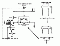
The pi filters are interesting.
You mean R-C112? 2-pole at 4KHz. No annoying top two octaves.
> the wire in red in the picture went from the pcb to the input selector switch, wich isn’t there anymore.
Ah. Let it dangle. It probably engaged only on AM, where a heavy 4KHz cut DOES make sense (moreso in Europe). Maybe for 78. You don't want it for FM or LP (or CD/DAC).
Last edited:
PRR, yeh the three legged 'resistors' with probably discrete cap(s) inside the tube (as I doubt there would be enough capacitance from a metalised inner tube). Don't recall coming across them before if they are old style resistors.
I might need your help for a little modification i’d like to do on the tone stack. I’d like to remove the loudness control, and to add a regular volume control instead. I think that the volume control would be better placed between the tone stack and the power amp than at the input, so my input impedance doesn’t vary with the volume. Let me know your opinion about that.
The help I most need is with the input caps values, and grid stopper resistor. Does it need a grid stopper resistor, and what value should it be ? I think that something like 47k and 0.22uf would be acceptable, but i’d like your input about that.
Finally, Do I need to add something else that I didn’t mentioned ?
Thanks again ! Your help is much appreciated !
> I think that the volume control would be better placed between the tone stack and the power amp than at the input, so my input impedance doesn’t vary with the volume.
If true: then the load on the tone control network would "vary with the volume". And the tone control is a lot more sensitive to load than any source you would plug into this.
Also putting the only gain-trim "late" in the amplifier chain risks overload before the vol pot. This one, even 2V peak input could put the gain stage at many-% THD.
IMHO: the Old Guys usually knew what they were doing. Study, don't jump in with the mod torch.
Whether you convert the Loudness to Volume (remove the tap parts) is your business. Personally, on such a small unpretentious amp, I'd leave (at least try) the Loudness.
> I think that the volume control would be better placed between the tone stack and the power amp than at the input, so my input impedance doesn’t vary with the volume.
If true: then the load on the tone control network would "vary with the volume". And the tone control is a lot more sensitive to load than any source you would plug into this.
Also putting the only gain-trim "late" in the amplifier chain risks overload before the vol pot. This one, even 2V peak input could put the gain stage at many-% THD.
IMHO: the Old Guys usually knew what they were doing. Study, don't jump in with the mod torch.
Whether you convert the Loudness to Volume (remove the tap parts) is your business. Personally, on such a small unpretentious amp, I'd leave (at least try) the Loudness.
I’ve tried it without any mods to the circuit, but it seemed like the loudness had some kind of impact on the low/high end of the sound. The loudness pot was making a lot of noise so I removed it anyway. I could try to put the one I added on the input, between the coupling cap and the grid stopper.
What kind of value would you use for the grid stopper ? I’ve used a 47k but I’ve been told that it might be too much, and that between 5k and 20k would be more appropriate.
- Status
- Not open for further replies.
