Hi Roar Malmin
I was send you the SM on 8th June. Did you received it or not?
Info for another guys: the SM you can get on www.ManualsCenter.com. It costs ca 16$.
JKoch
I was send you the SM on 8th June. Did you received it or not?
Info for another guys: the SM you can get on www.ManualsCenter.com. It costs ca 16$.
JKoch
Re: Post#39
Hi KP11520, & Jkoch
I am unable to receive the SM. I have asked this question :
"How can I receive an email as large as 26.6Mb via yahoo.com?"
One of the member of Yahhoo.com answered me that :
You can send via yahhoo messenger, or download from youtube.com .....
Being a new kid to internet (although my age is old 😀 ), I look forward to hearing advice from all who are expert on the subject of internet.
Best Regards.
Kong
Hi puqinfo and Baleuq
I just received infos from System Administrator: my message did not reach the following recipient(s)...
Regards
JKoch
I just received infos from System Administrator: my message did not reach the following recipient(s)...
Regards
JKoch
Hi Kong
Do not give up your attempt, of course. Tommorrow I will try to send it to YouTube.
Regards
JKoch
Do not give up your attempt, of course. Tommorrow I will try to send it to YouTube.
Regards
JKoch
Hi Keith,
Well, free opamps are useful!
Its in some ways safer to solder in sockets, because if you overheat anything with the iron, its just a socket pin, not a sensitive IC - although you;d have to be pretty unlucky to fry an opamp IMO.
I wouldn't worry too much about low DC offset, if you're going to bias into Class A, you'l probably be adding an offset - so don;t remove those caps unless you're certain you're amp has them at the input (very likely, but make sure you check).
It doesn't really matter how good you're muting transistors are, they'll be in the signal path, leaking small amounts of signal to ground if the conditions aren't right (basically distorting the signal, if there is a lot of PSU noise).
However, the eventual use of relays is a step in the right direction.
There's loads of different ways to provide a current source, I often use a couple of bipolars and a couple of resistors, with which I'm very happy. I might start using current mirrors in my next DAC, because I need quite a few current sources, and I need to keep my component count down a bit. Other people swear by cascode current sources.
I suggested a single fet and resistor, because it would be the easiest to do on an already populated PCB. It would get a bit tricky with more complicated solutions trying to sensibly attach it to the PCB (probably the main reason that put me off class A biasing). If it was your own board, it would be much easier to do whatever you want. Besides, its a quick solution to see if it makes an improvement, so you can work out if you want to take ithat route further (better than spending ages on something to discover it doesn't help at all, or breaks stuff).
Sounds like you're on the right route though.
Good luck.
Phil
Hi Jkoch,
I like the 6172, I use it in my NOS DAC. It has very high bandwidth, so should be able to cope with a bitstream DAC's output well.
Don't forget the analogue supply requires a negative regulator as well, and I haven't found a negative equivalent to the 1085, but its a good regulator for what it is (better on paper than 78xx, or 317/337).
Also consider using inductors in place of safety resistors. They should be in series with the bypassing caps then and create CLC filters - this will help keeps noise borne interference within their seperate circuits, and not infect other circuits (it will help, but probably not cure).
The clock could be a simple decision (just pick whatever you want, and make sure it has a very quiet power supply) or a difficult one (trawl through all the threads on the subject and get thoroughly confused).
I use clocks that are similar to the Kwak Clock (basically a Collpitts oscillator feeding a comparator to convert square up the edges), basically because I have the bits to hand, and its fairly cheap and simple to do - but that suits me, and might not suit others.
Some clocks might be better than others, and I have no frame of reference, but if whatever you choose makes a noticable improvement, then that's great.
You can mod CD players a LOT, and get a great sound, but don;t spend too much time worrying about minor detail to start with.
Better gains are to be had in a general improvement of a player than just one specific one.
Again, sounds like a good route to take.
Cheers,
Phil
Hi Phil,
You are a gentleman and practical and I appreciate both!
You have taken more time to help me with your experience than anyone so far on this site!
Thank you!
Regards//Keith
You are a gentleman and practical and I appreciate both!
You have taken more time to help me with your experience than anyone so far on this site!
Thank you!
Regards//Keith
Blimey!
Glad to be of service.
They're just my opinions though. Do get other's too. It all helps.
Cheers,
Phil
Glad to be of service.
They're just my opinions though. Do get other's too. It all helps.
Cheers,
Phil
Hi Philpoole
Thank you for your detailed and long answer. I will first time use LT6172 based on other DIY opinions about its sounds. What do you think: I can repleace NE5532 by LT6172 without changes of any discrete elements or should I change any value of caps and resistors (I am not high experienced elecronic and I rather based on ready applications which I found in internet).?
I cannot find a complementary negative regulator to LT1085, but just I send the question to technical suuport on LT website. Maybe I will get any advice. If not, I intend to use 2x LM340T5 as positive and negative regulator. What do you think about the choice?
Repleacing all safety resistors by inductors is a good idea. I will try find suitable inductors in elfa.se.
About clock: I just start think about it and now I read many posts about clocks only. Could you present your clock in this thread? I might be very interesting to compare your clock to Kwak Clock.
About PSU: I intend to build external PSU and rebuilt internal PSU. The external will contains: trafos (2x 100VA toroid and 1x EI trafo demounted from CD950. My idea based on NAIM Supercap. The external PSU will give:
ACF1, ACF2, VFTD, AC3, AC4 from EI trafo,
+/-21VDC from first toroid for analog ICs,
+/-18V from second toroid for digital ICs.
Look at the attachment (of course I use only one GND to connect with CD950). There are:
RFI Filter,
bridges based on MUR860 (and RC series)
8x 15000uF-22000uF electrolytic caps,
8x 1uF metalized polypropylene caps,
8x 0,1uF ceramic caps.
In case of CD950 I fit regulated PSU for each voltage built on LT1085/?????.
The ex and in PSU are my first step to modification CD950.
Next steps will be:
build (or buy) better clock,
repleacement of op-amps,
repleacement many caps,
build new case with special antiresonance platform for CDM9,
new sockets (RCA, BNC, etc.)
It will be many work and need long spare time. So the CD950 will change to top-loader CD.
JKoch
Attachments
Hi Philpole
I just find few posts when DIYers claim that neg reg LT1033 is complementay to pos reg LT1085. What do think about the opinion?
JKoch
I just find few posts when DIYers claim that neg reg LT1033 is complementay to pos reg LT1085. What do think about the opinion?
JKoch
Hi,
I use the LM6172, made by NatSemi, not Linear, but they may well be very similar.
You should be able to swap them around. Be careful though, the 6172 is a very high bandwidth opamp and can oscillate if the surrounding electronics aren't very supportive. I think you'll be okay on a commercial board though. They're fine in the CD63 for instance.
You say you're not highly experienced in electronics. Be careful if you're going to build a power supply.
In the PSU schematics, your disconnecting network isn't quite right (clue: it currently doesn't disconnect anything). I'm no expert on PSUs, although I have built a few. There are loads of threads worth looking at. AndrewT has posted some great posts on PSU layout.
I've never encountered the LM340T5, so I can't really comment on it. Nice one finding the LT1033. I shall have to have a look at that one 🙂. Why not use the LT1085 for the digital supply?
My version of the Kwak Clock is basically single supply, with a seperate PSU and voltage regulator. Some of the signal filtering was adjusted (mainly because of components I had to hand) and the PSU is different - as described.
Its hardly a revolution. More a cost control (and an attempt to make it smaller).
Building a new antiresonance platform for the CDM9. Surely that must be a different project? Maybe it would be better to by a CDPro2 and controller board and start from scratch?
I'm not sure it would be worth the effort with a midrange player.
Having said that, I modded a CD63 for a friend, and it was comparable to his unmodded Micromega Stage 2, and some of those on the huge CD63 thread have some incredible players.
Cheers,
Phil
I couldn't put my finger on it earlier, but I think I've worked out what was bothereing me about the grounding on your PSU.
You shouldn't have the CDP ground going to one half of the reservoir caps' ground, while the others go to the centre tap of the transformer.
I think, you should have all the caps' grounded to a star earth (often a centre tap) and the ground from the CDP going there as well, not via the ground path of the reservoir caps.
That's my take on it, the grounding does need some work, but there are far more qualified people to comment on that than me.
Cheers,
Phil
Hi Phil
Of coures, it should was LM6172 (my mistake becouse I still thinking about LT regulators).
Maybe you have a right said that I should build CDP based on CdPro2 (VAU1254), but the projekt has I one defect: it cost ca 250-300EUR (with or without display). And second problem: for the CDPro2 I sould bulid DAC. Now I use AudioAlchemy DAC (DAC-in-the-box) + DTIPlus (Digital Transmission Interface Plus). The AA DAC is based on CS8412-CP + 2xAD1860N-K + OP275 and DTI+ are based on CS8412-CP + few 74AC/HCU. I do not know if the AA components will give me quality of sound like CDPro2 offered. I still have many doubts to give up CD950 projekt and start CDPro2 one. Till now I collected many opinion, materials and other details about CDPro2 but the price!
Regards
JKoch
That's precisely the same reason why I chose CDM9 in the form of CD940. CDPro2 is too expensive.
I haven't looked back yet. My stripped down CD940 'Transport' is a great transport, and can feed my DAC with pretty clean I2S.
I meant, if you're going to mechanically rebuild the CD950, you may as well start from scratch, IOW that's a fairly major undertaking.
I haven't looked back yet. My stripped down CD940 'Transport' is a great transport, and can feed my DAC with pretty clean I2S.
I meant, if you're going to mechanically rebuild the CD950, you may as well start from scratch, IOW that's a fairly major undertaking.
Hi All
Would Anyone Send These Schematics And Manuals To Me.
My Email:Md.samimi@Gmail.com
Thanks To All.
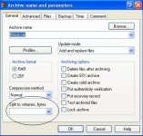
And If Files Are Too Large For Emailing You Can Compress Them And Generate Some Smaller Files From Them To Send.
For Example You Can Use WinRar And Use The ((Slip To Volumes,Bytes)) Option.
Would Anyone Send These Schematics And Manuals To Me.
My Email:Md.samimi@Gmail.com
Thanks To All.
And If Files Are Too Large For Emailing You Can Compress Them And Generate Some Smaller Files From Them To Send.
For Example You Can Use WinRar And Use The ((Slip To Volumes,Bytes)) Option.
Attachments
JKoch said:Hi Wckong
I just have sent the SM to you. QSerraTico Tico received the SM on 31st May, I hope.
JKoch
I did not receive the service manual. 🙁
Phil
I have a Philips CD820 buld on SAA7310GP, SAA7220P/B, TDA1541A R1, 2xLM833 and CDM4/19. Maybe it is better base then CD950 to modification? What do you think about the idea?
Regards
JKoch
I have a Philips CD820 buld on SAA7310GP, SAA7220P/B, TDA1541A R1, 2xLM833 and CDM4/19. Maybe it is better base then CD950 to modification? What do you think about the idea?
Regards
JKoch
- Status
- Not open for further replies.
- Home
- Source & Line
- Digital Source
- Philips CD950 schematics needed