1st stage
Ok, first stage is done.
All new electrolythics, LM6172 op-amps on the normal output (bypassed under), OPA2228 on the filtered out and headphones, I2S signals on the remote Din plug .
.
I must say I'm impressed with the sound.
It seams like good vinyl.
Even with the standard TDA1541.😱
Beautiful.
Ok, first stage is done.
All new electrolythics, LM6172 op-amps on the normal output (bypassed under), OPA2228 on the filtered out and headphones, I2S signals on the remote Din plug
.I must say I'm impressed with the sound.
It seams like good vinyl.
Even with the standard TDA1541.😱
Beautiful.
Attachments
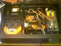
Got mine running again.
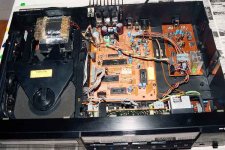
You can see some differences between yours and mine: there was the extra pcb (red) above the main pcb with the main cpu.
I killed that cpu, but got a replacement (from a forum member). But now also the new version, without the pcb. So i have some more space. I was looking at making a new smaller main pcb but now i think i wont do this anymore. There is a bit more space now to put something above the main pcb.
As you also can see, i took the display powersupply from the filter pcb and made a small new pcb for it. When i do something with the dac powersupply, i will put it together with that on a new pcb.
But that requires the powertransformers outside the case in a separate box, is for later.
Now looking at the output first. 1:15 transformer should give me 2.1V rms when i use the two dac's in differential mode with 50 ohm resisters to gnd (by connecting the transformer to both dac outputs and not to gnd, i avoid DC on the transformer, which it cannot handle).
I also have a marantz cd40 now to play with (cdm4,saa7310,7220,tda1541a R1) First thing i did was putting an eringa filter in (separate i/v conversion pcb with opamps. Same principle as normal output, just better components. Eighties stuff btw). I shortend the original opamp input.
......and it did not work anymore! Well shortening the inputs is not a good idea: the opamps are drawing too much current, the powersupply collapses and the transport decoder chips don't get enough power: no go. After cutting the resistors in the opamp powerlines, all is well again!
Greetings,
Guido
Hi, Guido!
(a little tread-jacking):
Since you mentioned it;
I have just got a CD-16 in house, and I'm itching for doing some tweaks....Op-amps & "output"-caps are obvious, as is a kwack-clock, what next?
Arne K
(a little tread-jacking):
Since you mentioned it;
(+SAA7310 & SAA7350)More exotic: CD11LE CDM15,CDM16: CDM4, TDA1547 and HDAM.
I have just got a CD-16 in house, and I'm itching for doing some tweaks....Op-amps & "output"-caps are obvious, as is a kwack-clock, what next?
Arne K
guido said:
As you also can see, i took the display powersupply from the filter pcb and made a small new pcb for it.
Hi Guido.
BTW, thanks for the schematic.
Instead of making a new CPU for the display, I was thinking in cutting the original board.
Looking at it, it's not a straight line, but I think I can cut the PB in two right next to the two big connectors.
Removing the filter board I'll have room for other things.😉
Arne,
Dont know really, never saw a '1547. The 7310 is the decoder, you need that one. the 7350 is a complete dac, but i think it is only used for the dig filter part inside.
What i can think of:
replacement of 7350 with better filter
replacement of opamp with better output circuit (fet/tube/transformer?)
But i have no experience with the 1547, or with other dig filters.
Maybe leave it as it is after the component upgrade ??
GuidoB
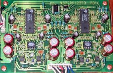
Looks like one is used for each channel. So there must be some logic for the i2s 'split'. Seems to be the little smd's in the top-middle. Connector on the left from the 7350 supplying oversampled i2s.
What are the typenumbers on those smd's??
Guido
What are the typenumbers on those smd's??
Guido
Thats nice!
I have a CD40 - I think it's a damn fine player,
with tons of potential to be made better.
I'll probably look at the power supplies and the clock first though.
IV side of things can come later.
Jim.
I have a CD40 - I think it's a damn fine player,
with tons of potential to be made better.
I'll probably look at the power supplies and the clock first though.
IV side of things can come later.
Jim.
Jim,
Be carefull with the pcb. The tracks come loose when you already look at them. The 650 is much better for diy there. That pcb is eightees stuff. OP42 as i/v and 5534 as outputbuffer. But relays for muting and deemph and good quality caps. PS = lm 317/lm337.
About the 1547, it's not i2s (saw the datasheet in the other post and it is already mentioned there).
There is a separate line for left and right channel (1 bit data).
So an inverter is enough to make it differential (like i2s dataline), but you don't need to split left and right.
Just left data + inverted to one dac as left and right input and right data + inverted to the other dac. Simple. Guess there is some reclocking on that pcb too (remove inverter delay, it is high speed)
Greetings,
Guidob
How about the Philips 850mkI and mkII
Philips 850mkI=Marantz CD 52 or CD 72
There are mkI and mkII versions of both the 52 and 72.
Philips 850mkI=Marantz CD 52 or CD 72
There are mkI and mkII versions of both the 52 and 72.
I have a Marantz CD52 SE.
It's good as a transport if you intend to make a Dac for it (even internal) with I2S connection.
As it is, the CD52/SE is nothing special, even tweaked, because of the Bitstream Dac.
The 72 is Bitstream too, I think it uses the TDA1547, the "famous" Dac7.
My CD650 is MUCH better with the internal TDA1541 in NOS mode.
Prometheus said:How about the Philips 850mkI and mkII
Philips 850mkI=Marantz CD 52 or CD 72
There are mkI and mkII versions of both the 52 and 72.
Can you describe how you modified your CD650 in details?
CD650 Mods and Issues
Hi all,
I'm a new member here.
I've been a tech for over 25 years, and now repair/restore anything HiFi, usually B&O, Grundig and Philips, and preferably pre-1990's.
Tube equipment is adored.
I have a highly modded CD650 here, which I will post photo's later, but I have 2 interesting problems with it.
Problem 1:
The drive is a dynamic CDM2/10, which (get this!) reads any and all CD-RW's perfectly, BUT on SOME normal factory, unscratched new CD's, the TOC is displayed, but immediately thereafter, the Red Disc Error appears - no further play is possible.
I have adjusted the R3106 to give 50mV across R3102.
So, because it reads CD-RW problem-free, I am not convinced that the problem is in the Laser.
Comments?
Problem 2:
After loading a disc, TOC appears normally.
Pressing the PLAY button "doesn't work".
But, if I start the playing with the SCAN button, and then press PLAY to cancel the SCAN function, the SCAN light extinguishes (playing continues).
So that means that the physical PLAY button itself is OK.
Also, pressing PLAY on the Remote control, does not generate a reaction, so the problem may be electronic.
I am thinking that the MAB8461PW079 is faulty.
Does anyone have any pointers for these 2 problems?
Thanks
M Yachad
Hi,
Have you tried putting the CD650 into service mode with one of the CDs it won't work with? These older CDPs don't seem to show error codes, but it would be interesting to see if it will output audio data in service mode 3, while it is operating at a basic level.
Anton
(and yes, amc184 here is amc184 on eBay)
- Status
- Not open for further replies.
- Home
- Source & Line
- Digital Source
- Philips CD650