Hello,
I have a decent CD610 player and wish to improve it. It already performed some of the usual tweaks: bigger caps, bypass with film caps, OPamp change (both I/V and output), better crossover caps...
I would like now to try reclocking, thanks to a new clock with a separate transformer.
Seems like this CD use TDA1543 + SAA7220GP + SAA7310, as well as MN4264P ( http://www.datasheetcatalog.org/datasheets/1150/499440_DS.pdf )
The oscillator is connected to pins 10 and 11 of the SAA7220
SA7220GP datasheet:
http://www.datasheetcatalog.org/datasheet/philips/SAA7220.pdf
Pin 10 of SAA7220GP is "XOUT": crystal oscillator output: drive output to clock crystal
Pin 11 is: "XIN" crystal oscillator input: input from crystal oscillator or slave clock.
My clock has a frequency divider so that I can chose frequency according to the crystal (from 33...mHz to 8....mHz, so I have "1/3" and "ground".
Which has to be connected to pin 10 ?
What do I need to remove or cut to power my clock with its own transfo ? The clock has its own regulation board.
Many thanks !
I have a decent CD610 player and wish to improve it. It already performed some of the usual tweaks: bigger caps, bypass with film caps, OPamp change (both I/V and output), better crossover caps...
I would like now to try reclocking, thanks to a new clock with a separate transformer.
Seems like this CD use TDA1543 + SAA7220GP + SAA7310, as well as MN4264P ( http://www.datasheetcatalog.org/datasheets/1150/499440_DS.pdf )
The oscillator is connected to pins 10 and 11 of the SAA7220
An externally hosted image should be here but it was not working when we last tested it.
An externally hosted image should be here but it was not working when we last tested it.
SA7220GP datasheet:
http://www.datasheetcatalog.org/datasheet/philips/SAA7220.pdf
Pin 10 of SAA7220GP is "XOUT": crystal oscillator output: drive output to clock crystal
Pin 11 is: "XIN" crystal oscillator input: input from crystal oscillator or slave clock.
My clock has a frequency divider so that I can chose frequency according to the crystal (from 33...mHz to 8....mHz, so I have "1/3" and "ground".
Which has to be connected to pin 10 ?
What do I need to remove or cut to power my clock with its own transfo ? The clock has its own regulation board.
Many thanks !
http://www.ne.jp/asahi/sound.system/pract/self_t_ev/cd-95.htm
I don't read Japanse, but judging from the first four pictures I'm guessing these guys are doing the same as you. If so, I think the pictures might give you the answer...
I don't read Japanse, but judging from the first four pictures I'm guessing these guys are doing the same as you. If so, I think the pictures might give you the answer...
Thanks for the hand, but this link sadly does not help much. Still don't know where I have to plug what 
Around pins 10 and 11 of the SAA7220 there is normally a crystal, two caps (probably SMD) and a resistor, connected as shown in the 7220 datasheet (page 17, Fig. 9).
Remove the crystal and the caps (I think the resistor can stay in) and connect the output of your clock to pin 11 (XIn).
- Your clock's ground must be connected to the player's ground
- Your clock must give 11.2896MHz
- Your clock will need a supply; you said it has a dedicated transformer, so you should be ok. There is nothing you have to cut from the original circuit, it is kind of a "passive" oscillator.
Hope this helps...
_
The same rules apply as for your previous postings in the CD723 thread.
Follow the suggestions in the above post.
Andy
Follow the suggestions in the above post.
Andy
pilli said:Around pins 10 and 11 of the SAA7220 there is normally a crystal, two caps (probably SMD) and a resistor, connected as shown in the 7220 datasheet (page 17, Fig. 9).
Remove the crystal and the caps (I think the resistor can stay in) and connect the output of your clock to pin 11 (XIn).
- Your clock's ground must be connected to the player's ground
- Your clock must give 11.2896MHz
- Your clock will need a supply; you said it has a dedicated transformer, so you should be ok. There is nothing you have to cut from the original circuit, it is kind of a "passive" oscillator.
Hope this helps...
_
Thanks a lot.
So I would have to remove the black SMD + the two green/green SMD chips ?
deuginthesky said:So I would have to remove the black SMD + the two green/green SMD chips ?
...sorry, I don't know the 610 in particular.
You have to remove three things:
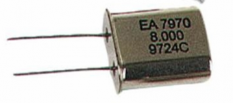
One quartz crystal. This is not SMD, it is a rather large (say 2cm tall) shiny metal can with "11.2896" marked on it. I think it is in the picture you posted the shiny thing at the lower right corner, below the 7220.
Actually I'll attach a picture of an 8MHz quartz can.
Two capacitors. To identify them try to map the schematic to the actual circuit. They might be on the opposite PCB side to the crystal.
Maybe the black SMD thing is the resistor?
(sorry if this is all very "open doors", but there is a time before you know things and they look strange, and then you learn them and they look obvious...)
_
Attachments
@deuginthesky
You're crystal (Xtal) is the metal can closest to pins 10 and 11 of the SAA7220. On the solder side (your first picture) you can see an SMD-resistor very close to the pins of the Xtal. I think I can just read 224 (meaning 22 * 10^4 = 220 kOhm). Then on the right side of the resistor there is one capacitor, the other one is the similar looking one located one on the other side of the row of pins of the SAA7220. Hope that helps in recognizing the components you need to remove...
You're crystal (Xtal) is the metal can closest to pins 10 and 11 of the SAA7220. On the solder side (your first picture) you can see an SMD-resistor very close to the pins of the Xtal. I think I can just read 224 (meaning 22 * 10^4 = 220 kOhm). Then on the right side of the resistor there is one capacitor, the other one is the similar looking one located one on the other side of the row of pins of the SAA7220. Hope that helps in recognizing the components you need to remove...
I mesured the black chip as a 210K resistor, so with the +/-5% tolerance this is a 220K as you stated.
Ok for the removal.
Clock is this one
So the "1/3 = 11,28mHz" to be connected to the pin 11 of SAA
grd to pin 10 of SAA.
Is that it ?
I ask dumb questions but I don't want to freeze the SAA7220 or something else.
Thanks a lot to all of you
EDIT: what's annoying me is the "ground" on the clock board. If it refers to output then okay, but what if it's really a ground point, where do I get the clock output ?
Ok for the removal.
Clock is this one
An externally hosted image should be here but it was not working when we last tested it.
So the "1/3 = 11,28mHz" to be connected to the pin 11 of SAA
grd to pin 10 of SAA.
Is that it ?
I ask dumb questions but I don't want to freeze the SAA7220 or something else.
Thanks a lot to all of you
EDIT: what's annoying me is the "ground" on the clock board. If it refers to output then okay, but what if it's really a ground point, where do I get the clock output ?
GND should be connected to pin 12 of the SAA. Pin 10 should be left open. You get the clock (goes to pin 11 of the SAA) at 1/3 Fo.
oshifis said:GND should be connected to pin 12 of the SAA. Pin 10 should be left open. You get the clock (goes to pin 11 of the SAA) at 1/3 Fo.
Thanks so much ! I plugged it the way you adviced me, and it works perfectly.
For the moment the clock is powered by the main 4700µF 35V capacitor (bypass with a 1,5µF film cap), but I would like to use a rather big 12V transfo I have.
I need to find a decent +12V regultor board so that I can feed the clock with clean 12V DC.
If you don't mind some DIY with the soldering iron, then building you're own 12 V supply is easy. You only need a handful of components.
Easiest (maybe not the best, though) to use is a 7812 and a few capacitors. It needs at least 15 V to work properly but after rectification your 12 V (AC) transformer will supply 15.6 V DC (12*√2 - 1.4).
If you don't like the idea of building one from scratch, you could go for a kit based around a LM317, like this one.
hi deuginthesky!
I aslo own a cd610. Can you elaborate on the changes you already made?
Cheers
Stephan
I aslo own a cd610. Can you elaborate on the changes you already made?
Cheers
Stephan
Bigger power caps with low esr
bypass of main caps with MKT film caps
faster diodes
bigger caps after the regulators (mostly 470µF very low esr)
Silmic II on signal path
AD825 ou 827 for I/V
LM4562 as output
Better quality caps (mica and styroflex) for bypass of I/V AOPs
+ the clock
No separate PSU for the TDA or the clock however.
MFG 😉
Thanx!
But that's the operations manual - already got that.
I'm looking for the service manual, wiring diagram, etc.
Cheers
Stephan
But that's the operations manual - already got that.
I'm looking for the service manual, wiring diagram, etc.
Cheers
Stephan
- Status
- Not open for further replies.
- Home
- Source & Line
- Digital Source
- Philips CD610 recloking