jives11 said:
Thanks.
Q: I took a look at the servo board. In addition to 2 obvious solder hills covering griplets, I noticed that a couple of the axial caps and at least two wire links had large solder mounds at one end. Do these also cover griplets and should these also receive the treatment ?
See attachment. I think I have marked all the gripleta and through holes.
Andy
Attachments

Thanks poynton, yep - those look like the ones at the ends of wirelinks and axial caps.poynton said:
See attachment. I think I have marked all the gripleta and through holes.
Andy
jives11 said:
Thanks poynton, yep - those look like the ones at the ends of wirelinks and axial caps.
There are also many on the decoder pcb. Have you done those as well?
Andy
poynton said:
There are also many on the decoder pcb. Have you done those as well?
Andy
Not done any yet, but earmarked for this weekend. Replace all on both boards.
BTW - while the lid is off I want to try and fix a problem with the drawer mostly not fully retracting. The poor thing has to be helped to close. I'm guessing this is the rubber belt from the motor to the sled mechanism slipping.
Has anyone found a cure ? The belt appears to be tricky to remove without taking aprt the whole motor casework.
Has anyone found a cure ? The belt appears to be tricky to remove without taking aprt the whole motor casework.
jives11 said:BTW - while the lid is off I want to try and fix a problem with the drawer mostly not fully retracting. The poor thing has to be helped to close. I'm guessing this is the rubber belt from the motor to the sled mechanism slipping.
Has anyone found a cure ? The belt appears to be tricky to remove without taking aprt the whole motor casework.
This fault rectifies itself with heavy use.
Re: cd 104
http://user.planetaclix.pt/
ampere said:Hy can anibody help me with some schematics or another documents about CD 104 ?
http://user.planetaclix.pt/
If that site sends you a 3MB version then it is incomplete. I have the (Ihope) complete manual. I can send it but it is 10MB.
Let me know....
Jeroen
Let me know....
Jeroen
JeroenR said:If that site sends you a 3MB version then it is incomplete. I have the (Ihope) complete manual. I can send it but it is 10MB.
Let me know....
Jeroen
Hi.
I would like a copy if you can send it to me.
Thanks.
Andy
Please send me your email. I used the mail facility here but did not spot directly an attachment button. 🙂
Oh, it is 12MB.
Jeroen
Oh, it is 12MB.
Jeroen
JeroenR said:Please send me your email..
Jeroen
I would but your email is not enabled!
Andy
Many thanks to Jonathan I. for the documents.
Is anybody interested to put tubes in the CD 104 analog output?
Is anybody interested to put tubes in the CD 104 analog output?
ampere said:Many thanks to Jonathan I. for the documents.
Is anybody interested to put tubes in the CD 104 analog output?
HI.
I have just 'finished' a tube output stage for my CD63. I found this article very helpful.
http://www.fortunecity.com/rivendell/xentar/1179/theory/vasfda/vasfda.html.
Does someone have a complete pdf of the CD104??
Andy
JeroenR said:email should be enaled now.
And... Tube output? Where? There's not a lot of room inside. 🙂
Yep , it is tight for space !!!
I will make a mock-up tomorrow and post the photos.
Andy
poynton said:
Yep , it is tight for space !!!
I will make a mock-up tomorrow and post the photos.
Andy
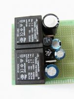
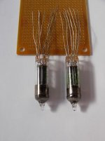
OK - I have cheated a little but it is possible ! ( for one thing, I did not build it!)
Using circuit similar to :-
http://myweb.tiscali.co.uk/nuukspot/decdun/cd723vosdiagrams.html
Or the web page above,
The board will fit under the Decoder PCB - over 1cm of room - on stand offs fixed to the ground plane. The largest component is the output cap but that depends on your choice.
If the opamps and associated components are removed, you get more space. As the output muting is by relay, I am in 2 minds as to whether they should be removed or not!
Obviously, the existing output cable will be removed and replaced with Quality sockets.
Attachments

Tube Output for CD104
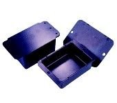
The power supply will have to sit outside at the rear in a platic box. It may be possible to fit the regulators on a small board inside.
poynton said:
Yep , it is tight for space !!!
I will make a mock-up tomorrow and post the photos.
Andy
The power supply will have to sit outside at the rear in a platic box. It may be possible to fit the regulators on a small board inside.
Attachments
- Home
- Source & Line
- Digital Source
- Philips CD104 tweaks