I don't really understand the practical need for a LPF filter at a Q of 85-90kHz (usual values) when nobody can hear above 18-20kHz. I see just added stages and more components in the sound path 🙂
wrong! any unwanted signal will cause unwanted problems
remember when stereo pilot signal 19kHz on the output cause whistles in the tape recorders? do you want to overload input into next stages? do you want to cause high frequency oscillations in your amplifier? do you want to burn tweeters? do you want to scare and irritate house pets? go for it! fine with me
Last edited:
I don't really understand the practical need for a LPF filter at a Q of 85-90kHz (usual values) when nobody can hear above 18-20kHz. I see just added stages and more components in the sound path 🙂
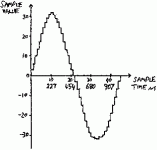
Figure 1: 1 KHz Sine Wave, -60db, 16 bit, 44,100 samples/sec
The output of the DAC (Digital to Analog Converter) in a CD player is not a continuous waveform. It has distinct steps which occur at the conversion frequency. A 1 Khz sine wave reproduced at a level of about -60 db uses 6 bits, and appears at the output of a DAC without over-sampling as shown in figure 1. Incidentally, the same wave at the same level coming off a Vinyl LP would be almost totally masked by surface noise. The Fourier analysis of figure 1 reveals a large number of extraneous high frequency components, which are sum and difference products of harmonics of the 1 Khz sine wave and a square wave at the sampling frequency.
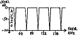
Figure 2: DAC Output Spectrum, No Over-sampling
A signal with components covering the entire audio range (music) produces the DAC output spectrum in figure 2. It is fairly obvious that we only wish to pass frequency components out of the CD player which were originally encoded on the CD. Also, if any of the high frequency garbage gets into later audio stages, lots of problems will occur, such as instability, intermodulation distortion, overheating and damage to wide-band power amplifiers and tweeters. The solution is to use a low pass filter to eliminate all the out-of-band components, leaving the audio signal perfectly intact.
Attachments
This and other similar threads could be summed up as
"I don't understand digital audio. I don't understand analogue audio. I don't understand mixed-signal PCB design. Please help me 'improve' my CD player by cutting out all the parts I don't understand."
"I don't understand digital audio. I don't understand analogue audio. I don't understand mixed-signal PCB design. Please help me 'improve' my CD player by cutting out all the parts I don't understand."
As far as I know the main reason forum exists is to help other people. If you don't want to help I don't know why you keep posting in this thread. I was expecting more from DIYAudio....
I have given you significant help. I have told you what the two opamps do. I have told you what you need to work out. I am trying to help you avoid damaging your CD player and sound quality.
Perhaps you don't want help; you just want affirmation?
Anyway, as you clearly don't think you need my help I will leave you to do whatever you think best. It's your CD player and your music. However, in future please remember that on a public forum like DIYaudio if you ask a question you must not be surprised if some of the answers you receive are true but inconvenient; if you merely want convenient but untrue answers then there are other audio forums where this is more likely to occur.
As far as I know the main reason forum exists is to help other people.
I suppose there are 2 things you can do to help you modify the analog stage:
1. Learn about analog amplification and in particular the OP implementation in analog stages (start with "differential to signle-end OP implementations")
2. Learn about power supply decoupling techniques
(3.) Learn about mixed signal PCB design principles and don't skip on articles that talk about frequencies into gigahertz region.
This should in fact be a great fun because all the knowledge gained could be implemented immediately by trying the mods inside your player. Even few articles / white papers will help you broaden your understanding.
You were also a bit unlucky by being exposed to criticism, but don't feel like the life should stop -> it is up to you to gain the required knowledge to help you modify the player and achieve great results!
If you simply can't wait, then retain all gain sections and all the parts - just try different OP's. In addition, place the little 0.1uF SMD decoupling caps close to OP's Vcc / Vee pins. This should give fantastic results.
Regards,
Nick
Hey Nick,
Thanks for you contribution! I will leave all the gain sections and change the OPAMP's, hope the LME49720HA's will be a god replacement for the LM833 that it's used now.
I have a couple of questions:
1) I removed the muting transistors, but I'm left with resistor 3332 (10k to ground) and resistor 3334 (1k in the audio path). Should I keep them or not? I saw other designs that only have 100ohm or 200ohm in the signal line and that's all.
2) You are saying to put the 0.1uF cap close to the pins, but it wouldn't be better to use the design from the philips datasheet which have 47uF paralleled with 47nF on both Vcc and Vee rails?
Thanks for the help!
1) you can leave everything as is. Try AD827 and LM6172
2) there's an obvious need for you to read what I suggested in my previous post under 2. and (3.) Then apply what you learnt to your CD player. If done properly, this could make huge difference, that together with LM6172 could produce fantastic results...
2) there's an obvious need for you to read what I suggested in my previous post under 2. and (3.) Then apply what you learnt to your CD player. If done properly, this could make huge difference, that together with LM6172 could produce fantastic results...
Your starter
http://www.x2y.com/filters/TechDay0...log_Designs_Demand_GoodPCBLayouts _JohnWu.pdf
Plenty more info. regarding mixed signal layout, just done an analogue/digital board with 2200 components and 5000 connections 🙂 Great fun and five weeks of my life gone...
Go with the 100nF as Nick has said close to the pins, very close and then closer still, with uF caps near but not to close.
Yep... that's also why (too) modern and fast opamps can be a pain in the neck in older PCB's...Your starter
http://www.x2y.com/filters/TechDay0...log_Designs_Demand_GoodPCBLayouts _JohnWu.pdf
Plenty more info. regarding mixed signal layout, just done an analogue/digital board with 2200 components and 5000 connections 🙂 Great fun and five weeks of my life gone...
Go with the 100nF as Nick has said close to the pins, very close and then closer still, with uF caps near but not to close.
- Status
- Not open for further replies.
- Home
- Source & Line
- Digital Source
- Philips CD 750: advice for output stage rebuild