dear forummembers,
I have several Philips late 1920 and 1930 radio's.
Often do these tuberadios have and 506K or 1801 or 1805 rectifier tube.
But these tubes are beginning to end up out of stock.
Or really expensive $100 or more.
At this moment an AZ1 tube can be used to replaced them.
But if everyone usses that tube, soon or later these are also out of stock.
So i think it would be usefull to make a drop in replacement.
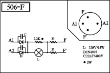
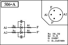
So i have done some searching on the internet, and have found the following replacements (see attached files).
but now i am wondering of these replacements are going to work fine.
And if this affects the lifespan of the other tubes.
Because a vacuum tube ractifier builds the high voltage over a period of time,
where these diodes are goning to directly give high voltage.
Is there somebody here that can give me some good advise?
Attachments
AZ41 could also work i think.
I dont think either 1805 or AZ1 are as scarce as you are led to beleive. On the radio marked in Driebergen AZ1 are plentifull, and even heavily used ones will allow a radio to play. Furthermore the radio collectors scene is rapidly ageing so in ten years time supply will be better than now.
I dont think either 1805 or AZ1 are as scarce as you are led to beleive. On the radio marked in Driebergen AZ1 are plentifull, and even heavily used ones will allow a radio to play. Furthermore the radio collectors scene is rapidly ageing so in ten years time supply will be better than now.
506, 1805 use Europe 4 pin B4 base. https://www.radiomuseum.org/tubes/tube_506.html
AZ1 available with side contact P8A base, AZ41 has Rimlock base B8A.
Both of them 4V filament tube, but with slightly different current.
AZ1 available with side contact P8A base, AZ41 has Rimlock base B8A.
Both of them 4V filament tube, but with slightly different current.
The 1805 is capable of rectifying up to 500Vac, so should really use two ss diodes in series for each of those replacement options. Also I'd recommend using UF4007 instead of 1N4007, as the perceived need for a parallel cap is avoided (and that cap is ambiguously specified as 400V rating, when it should be at least specified as 400Vac and preferably X rated, and is large and an unwanted risk imho).
Given those original diodes are directly heated, the equipment they have been used in will likely see a surge in B+ voltage, so there seems no imperative to use a delayed start form of replacement option.
Certainly any replacement with ss diodes needs to include added series resistance in the anode arms so that the power transformer and first filter cap are not stressed beyond their original use. The resistors in series with the F terminals appear to allow balanced current to flow if those two terminals remain connected to say a 4V winding. If the heater winding was disconnected completely then that is one option, however for a drop-in replacement then the two resistors may well avoid a possible situation of the B+ voltage also having 4Vac added to it.
Theres a small bulb variant of the 506 that is sought after for its lower profile. Theres a radio model from Philips that has a height restriction on rectifiers.


