
anyone ever heard these. how do you use this plug. any adapters or can i cut it off and add my own plug
My guess is you are asking about Philco Electrostatic Units that came with several different stereo console models (H-1714, H-1814, H-1816).
Currently there is a pair listed on ebay which appears to be where your plug picture came from.
Vintage Pair Mid Century Philco Stereo Phone Electrostatic High Freq Speakers | eBay
In any case, to work properly the unit needs audio signal fed to pins 2 and 3, and a high voltage bias supply connected to pins 1 and 5.(about 1kV). With audio signal hooked up, you should hear sound from the midwoofer whether or not you have a high voltage bias supply connected. You will only hear the high frequencies from the electrostatic tweeter once you connect the 1kV bias supply.
Attachments
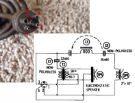
The print shows the Bias to be about -580v as I had expected.
Typically the ESL's of this era were driven directly off the plates of the tube amplifier.
They won't perform anywhere near as well as a DIY ESL using today's materials would.
But, I am sure they would be fun to listen to though.
A lot of radios and systems in those days came with some little 4"x 4" or so tweeter units in them, I have seen a few of them back in my days of repairing TV's and such tube equipment back in the 80's.
jer 🙂
Last edited:
The print shows the Bias to be about -580v as I had expected
The diaphragm is connected to a -580V supply.
But notice that the transformer center tap is connected to +370V.
So, the total bias voltage would be -950V.
Yes, You are correct I somehow missed the 370v connection to the transformer. He,he,he
Thanks!!! 🙂
jer 🙂
Thanks!!! 🙂
jer 🙂
Last edited:
Maybe the additive plus and minus voltages helps reduce the tension on the matching transformer for arcing.The diaphragm is connected to a -580V supply.
But notice that the transformer center tap is connected to +370V.
So, the total bias voltage would be -950V.
Despite being a strong advocate for direct drive HV amps, letting your high current capability B+ wander about the radio cabinet is a recipe for murder.
Some of these prehistoric ESLs were one-sided, something nobody has done since Hunt's book. I wonder if they really sound so bad? Not likely I'd notice harmonic distortion of 6 kHz fundamentals.
Ben
Last edited:
The little tweeters that I heard weren't anything spectacular, but they did add a bit of zing to an otherwise drab woofer in the old radio's and TV's of the day.
I took one apart and it had no supports for the diaphragm.
I was just layers of plastic films loosely layered between the plates so that it could vibrate.
There were three films, a metal coated diaphragm in the middle with two outside insulating layers of plastic film to insulate the center film from the bare copper stator pieces.
The whole thing was held together by two rivets in two adjacent kiddie corners in a square shallow plastic cup that mount to the speaker board by two screws in the opposite corners where there were no rivets.
I remember my boss getting mad at me for taking it apart for fear that it wouldn't work again, But it did work!! He,he,he,he
jer 🙂
Fortunately the B+ supply(and -580V) don't exit the chassis on their way to the ESL panel without first being current limited by a 2.2Mohm resistors.Despite being a strong advocate for direct drive HV amps, letting your high current capability B+ wander about the radio cabinet is a recipe for murder.
I recently re-read the Hunt book and noticed at the start of the section on push-pull ESLs he credits Philco for pointing him toward the push-pull, constant charge configuration. The footnote reads:Some of these prehistoric ESLs were one-sided, something nobody has done since Hunt's book. I wonder if they really sound so bad?
“Carlo V. Bocciarelli of the Philco Corp. suggested this circuit to us and argured qualitatively the advantages of constant-charge operation. The analysis given below shows the performance to be even better than predicted.”
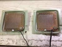
Unlike the ESL tweeter panel that started this thread, Philco’s first ESL tweeters were single-ended affairs like shown in the attached pic. Compared to dynamic drivers of the day, these ESL tweeter sound quite good on music. When I sweep them with test tones though, there is noticeable distortion and resonances present.
Attachments
Sounds like you are describing the Zenith ESL tweeters. Did they look something like this?The little tweeters that I heard weren't anything spectacular, but they did add a bit of zing to an otherwise drab woofer in the old radio's and TV's of the day.
…The whole thing was held together by two rivets in two adjacent kiddie corners in a square shallow plastic cup that mount to the speaker board by two screws in the opposite corners where there were no rivets.
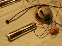
The later Philco ESL curved dipole panels were considerably larger, about 10” across.
Attachments
We are all very fortunate to have persons of great experience and knowledge (and generous in their posting) like bolserst and geraldfryjr.
Both comment that adding a bit of zing to the last octave is a good thing - even if "zing" means distortion and even if not quite fine by the usual standards of this forum.
Interesting to learn of the construction method using a sheet of mylar to insulate the moving diaphragm (and dampen and crap-up through contact). Sounds like an easy way to DIY ESL, providing the sound was good. I guess you could be working with very small, low-voltage gaps.
Still thinking of construction ease, I wonder if it would be much trouble for somebody to take a normal two-stator cell and bias it one-sided and measure the output?
About B+ tube voltages: with a direct-drive HV amp, you couldn't have 2.2 megOhm resistors protecting the user because that would cause frequency discrimination (but not be lethal). But using the B+ just for bias, it is OK to have those resistors for protection.
Ben
Last edited:
This reminds me of a patent I stumbled on a few years back that used two diaphragms (centered between push-pull stators) with conducting sides facing each other, so the conductive coatings are protected from the elements by the diaphragm itself. When bias is applied, the diaphragms being of like charge would repel each other and bow outwards toward the stators. The patent also claims improved diaphragm stability with low tension.Interesting to learn of the construction method using a sheet of mylar to insulate the moving diaphragm (and dampen and crap-up through contact).
Attachments
- Status
- Not open for further replies.
- Home
- Loudspeakers
- Planars & Exotics
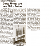
- Philco Stereo Phone Electrostatic