Hello folks!
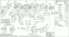
I've scavenged a working power transformer, output transformer and speaker from a very dead Philco 1224 Gramophone, and my plan is to build a small guitar amp using those as the core. This is my first attempt at design, so I've cobbled together a best-guess schematic which reinvents as little as possible. In that spirit, the rectifier, filtering and output sections have been lifted straight from the original schematic:

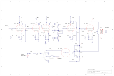
For the preamp, I've settled on a single-jack version of the typical Fender input, cascading a couple of 7F7 tubes, and thrown in the most copied tone stack of all time for good measure. This is what I have so far - I struggled to find appropriate symbols for all the necessary components, so please excuse the obvious substitutions:

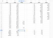
The matching BOM:

I want to start working on the component layout, but I suspect there are errors aplenty in the schematic due to my inexperience. I'm hoping that some more experienced people are able to look at my work and suggest improvements to the general topology and/or component values before I go further. Is there anything glaringly obvious about what I've got so far which you would do differently?
As I progress through the build, I'm also putting the source files up on Github too: https://github.com/akhumphrey/1224-amplifier
I've scavenged a working power transformer, output transformer and speaker from a very dead Philco 1224 Gramophone, and my plan is to build a small guitar amp using those as the core. This is my first attempt at design, so I've cobbled together a best-guess schematic which reinvents as little as possible. In that spirit, the rectifier, filtering and output sections have been lifted straight from the original schematic:

For the preamp, I've settled on a single-jack version of the typical Fender input, cascading a couple of 7F7 tubes, and thrown in the most copied tone stack of all time for good measure. This is what I have so far - I struggled to find appropriate symbols for all the necessary components, so please excuse the obvious substitutions:

The matching BOM:

I want to start working on the component layout, but I suspect there are errors aplenty in the schematic due to my inexperience. I'm hoping that some more experienced people are able to look at my work and suggest improvements to the general topology and/or component values before I go further. Is there anything glaringly obvious about what I've got so far which you would do differently?
As I progress through the build, I'm also putting the source files up on Github too: https://github.com/akhumphrey/1224-amplifier
I am following your project with interest! I would like to try a similar project for my axe-wielding son.
The DIYLC layout is appreciated; they are time consuming to get as neat as yours, with proper component sizes.
2 comments:
The DIYLC layout is appreciated; they are time consuming to get as neat as yours, with proper component sizes.
2 comments:
- Is it worth having a master volume control on the input so that gain and volume can be used together?
- Looking at those electrolytic caps, the layout is much simpler with a can cap with the 3 caps in one. Was that an option?
Thanks! I used a couple of existing DIYLC layouts for classic Fender amps (a 5F1 and a 5E3) as source material for my layout, so the board component sizes are really only a reasonable estimate. My layout feels like a tangled mess by comparison to those circuits! The only components I have in-hand right now are the filter capacitors and resistors - the sizes of those, at least, were measured by me so I'm more confident on 🙂
It should also be noted, I'm taking something of a gamble with this layout. In addition to my inexperience and the uncertainty around if the components/topology, the chassis (I foolishly purchased before finishing the work so far) leaves very little wiggle room. I really hope the estimates of the component sizes are close, or I'm going to have a very uncomfortable time trying to cram all this guff inside too-small a space! 😅
With respect to your comments:
- I suppose one could add another volume control earlier on, but I'm not sure how it would be implemented. The idea I took here was to copy the classic 5E3, where an early potentiometer acts as both volume and gain controls. The addition of the late volume before the power tube was my best guess at applying a master volume to make the gain more usable.
- I'll confess I didn't even look to see if a can cap in the original spec was still available. My immediate thought upon seeing the can cap in the schematic was replacing it with multiple filter caps. I would imagine that if a can cap of the required spec was still available somewhere, it would be ridiculously expensive and/or difficult to obtain, with the bonus of being more difficult to maintain in future. That said, if you did have access to the right sort of can cap, then you could definitely revert my replacements and use the original spec.