Hi all,
I am exploring the World of interstage / signal transformers, especially as phase splitters.
Cheap-skate as I am, I wonder if there are good alternatives for reasonable money ?
But apart for the financial investment, I thought of the ways to connect an interstage,
see attachment.
I wonder if my assumptions are correct !
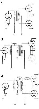
Option one;
No need for a coupling cap (which is a good thing) but risk of core saturation due to DC
in primary coil (especially when using cheap iron) Fidelity depends on quality of transformer
Option two;
Saturation-risk greatly reduced as DC is blocked from primary coil, by reintroducing the
coupling cap. Fidelity depends on quality of transformer and quality of coupling cap.
Option three;
Transformer used as single coil, a centre tapped choke actually.
Need for coupling cap, and compensation for resistance in coil for the inverted signal.
Fidelity is affected by the coupling cap and matching the signal-level through series resistor,
but not by the quality of the transformer. One should watch for a possible low pass filter
created by the values of the coupling cap and the induction of the coil.
Please correct me where I’m wrong !!
Cheers,
Empee
I am exploring the World of interstage / signal transformers, especially as phase splitters.
Cheap-skate as I am, I wonder if there are good alternatives for reasonable money ?
But apart for the financial investment, I thought of the ways to connect an interstage,
see attachment.
I wonder if my assumptions are correct !
Option one;
No need for a coupling cap (which is a good thing) but risk of core saturation due to DC
in primary coil (especially when using cheap iron) Fidelity depends on quality of transformer
Option two;
Saturation-risk greatly reduced as DC is blocked from primary coil, by reintroducing the
coupling cap. Fidelity depends on quality of transformer and quality of coupling cap.
Option three;
Transformer used as single coil, a centre tapped choke actually.
Need for coupling cap, and compensation for resistance in coil for the inverted signal.
Fidelity is affected by the coupling cap and matching the signal-level through series resistor,
but not by the quality of the transformer. One should watch for a possible low pass filter
created by the values of the coupling cap and the induction of the coil.
Please correct me where I’m wrong !!
Cheers,
Empee
Attachments
Empee,
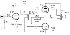
I don't have a lot of experience with transformers as phase splitters (or for that matter phase splitters in general) but I just completed a PP EL84 amp using autoformers as the phase splitters. This is most similar to your option 3 but cleaner in practice than your posted schematic. It does require a coupling cap.
I purchased the autoformers from Electra-Print. Jack designed the specifically for this purpose. They work extremely well and the amp sounds very good. IIRC they were about $56 US each.
It isn't the cheapest solution. A tube phase splitter can be done for less but with the accompanying issues of additional wiring, power supply considerations including heaters etc. This autoformer solution is very clean.
I've attached the schematic.
Attachments
lookin' good !
power of simplicity 😎
I really like to know, in the way your transformer is coupled, (same as my Option 3), how much the fidelity depends on the quality of the iron, since you're basically only using the coil...
...or am I completely wrong in this !?
Cheers,
Empee
power of simplicity 😎
I really like to know, in the way your transformer is coupled, (same as my Option 3), how much the fidelity depends on the quality of the iron, since you're basically only using the coil...
...or am I completely wrong in this !?
Cheers,
Empee
Empee,
Also inexpensive is to phase split at input. I have had great luck with the Edcor WSM10K/10K at $10 each in the U.S. I know there is an Edcor European distributor which could be in your home country.
I usually direct couple to the push-pull finals from input to save on the cost of a pair of caps, like here
Matt
Empee said:Hi all,
:::Option one;
No need for a coupling cap (which is a good thing) but risk of core saturation due to DC
in primary coil (especially when using cheap iron) Fidelity depends on quality of transformer::::
although not shown in your schematic as drawn--- this arrangement does in fact have (in 99 percent of apps) a capacitor in the signal path. The last cap in your power supply is clearly in the signal path--- and almost always will be larger in value than a blocking cap as used in a properly designed parafeed application.
::::Option two;
Saturation-risk greatly reduced as DC is blocked from primary coil, by reintroducing the
coupling cap. Fidelity depends on quality of transformer and quality of coupling cap.:::::
to illustrate the point I make above--- in this drawing move the blocking cap from the top leg of the IT's primary and put it in the bottom leg to ground. this is the same spot where the capacitor is located as in drawing #1. but it will likely be much smaller in value. Other benefit is that (instead of the plate load resistor as shown) you can use a C4S or large plate choke in place of the anode loading resistor--- and get much better power supply rejection.
:::Option three;
Transformer used as single coil, a centre tapped choke actually.
Need for coupling cap, and compensation for resistance in coil for the inverted signal.
Fidelity is affected by the coupling cap and matching the signal-level through series resistor,
but not by the quality of the transformer.::::
several thoughts here. In this discussion we are treating the phase splitting autoformer generically--- but much depends on the actual design quality of the device not on a generic analysis----
for example--- the two halves of the autoformer phase splitter can have identical DC winding resistance btwn the two halves. And the design can be arranged that the capacitive reactance btwn the two halves is largely identical.
And if the two half windings (driven vs induced) are interleaved you can have very high degree of coupling btwn the driven half and undriven half windings. Recall--- that in say example #1 and #2 we must have tight coupling (i.e., controlled leakage L) btwn the primary and secondaries to get good results.
the autoformer phase splitter can likewise be interleaved to promote greater coupling. In a unit that we make the amplitude differential (the output from the two windings) at 20khz is less than
two tenths of a db. Not so bad at all--- I'd say.
::::One should watch for a possible low pass filter
created by the values of the coupling cap and the induction of the coil.:::::
you also have to watch out for theis "low pass filter" in any design where you have a capacitance and an L. Your example #1 will have a resonance from the L of the tran's primary and the last cap in the power supply interacting with each other. The trick and goal is to get the resonance well outside of the audio band.
You did a nice job in graphically laying out your options. the only other advice I'd offer is that in example #3 you appear to have drawn say a conventional two winding trans and that one of the windings is unused--- your only using the center tapped winding--- the unused windings are very likely to hurt the coupling btwn the secondary halves (one driven--- one induced) since they are most likely interspersed btwn the primary.
If your going to go with #3---- you really need to get a transformer that was designed from the ground up as a phase splitting autoformer.
there has been a lot of discussion of autoformer phase splitters on our MQ forum over at Audio Asylum.
Here is a schematic that I had put up on the MQ forum maybe a week or so ago.
http://www.q-audio.com/images/el84amp2.jpg
Mike
Re: Re: phase splitting transformers
Mike is correct, but you could try this as a way to eliminate the large cap from the signal path and still use a single feed design.
Obviously, the output stage as drawn is single ended, but you could do a push-pull stage instead without change to the driver. More info on the design at http://www.ecp.cc/SSS.html
Also, you could make the driver differential with an input transformer: http://nutshellhifi.com/triode1.html
MQracing said:although not shown in your schematic as drawn--- this arrangement does in fact have (in 99 percent of apps) a capacitor in the signal path. The last cap in your power supply is clearly in the signal path--- and almost always will be larger in value than a blocking cap as used in a properly designed parafeed application.
Mike is correct, but you could try this as a way to eliminate the large cap from the signal path and still use a single feed design.
An externally hosted image should be here but it was not working when we last tested it.
Obviously, the output stage as drawn is single ended, but you could do a push-pull stage instead without change to the driver. More info on the design at http://www.ecp.cc/SSS.html
Also, you could make the driver differential with an input transformer: http://nutshellhifi.com/triode1.html
Sherman said:Empee,
I've attached the schematic.
this schematic was previously discussed--- see Jane's post and other posts from the earlier discussion.
http://www.diyaudio.com/forums/showthread.php?postid=1396766#post1396766
the concern with this particular schematic as shown is that the resonance is at 50 hertz from the published specs for the trans and the size (1 mfd) coupling cap shown in the schematic.
here is a really handy LC calculator---
http://www.opamplabs.com/cfl.htm
with a 1 ufd blocking cap your primary L of the driven half winding would need to be approx 253H to get the resonance down to 10 hz.
alternately, with a 10H inductance the C would need to be approx 25 uf to get the resonance down to 10 hertz.
MSL
the concern with this particular schematic as shown is that the resonance is at 50 hertz from the published specs for the trans and the size (1 mfd) coupling cap shown in the schematic.
And as i pointed out in that thread, the Electraprint seems to use a designed resonance to compensate for its low inductance. Not a problem then as it gives a relatively flat response down to below 50hz.
Doing your phase splitting at the front end is by far the cheapest option.
Shoog
Re: Re: phase splitting transformers
Hi !
Thank you all for the replies!
Yes,
that's the idea...
I got a couple of Hammond 124A's
from wich I really doubt they are any good.
But as I was thinking;
if I connect the 'formers as in option #2 or #3, I'd probably get
the best fidelity since I'm not putting stress on the iron as in DC
terms.
But I am still wondering how much the reactence half of the sec.
winding is relying on induction from the iron core
Less than options #1 and #2, I think 😕
Cheers,
Empee
Hi !
Thank you all for the replies!
MQracing said:(...) If your going to go with #3---- you really need to get a transformer that was designed from the ground up as a phase splitting autoformer. (...)
Yes,
that's the idea...
I got a couple of Hammond 124A's
from wich I really doubt they are any good.
But as I was thinking;
if I connect the 'formers as in option #2 or #3, I'd probably get
the best fidelity since I'm not putting stress on the iron as in DC
terms.
But I am still wondering how much the reactence half of the sec.
winding is relying on induction from the iron core
Less than options #1 and #2, I think 😕
Cheers,
Empee
Re: Re: Re: phase splitting transformers
Electra-Print also has these same autoformers with an M6 core. According to Jack these are able to handle higher signal levels.
Empee said:
...
But as I was thinking;
if I connect the 'formers as in option #2 or #3, I'd probably get
the best fidelity since I'm not putting stress on the iron as in DC
terms.
But I am still wondering how much the reactence half of the sec.
winding is relying on induction from the iron core
Less than options #1 and #2, I think 😕
Cheers,
Empee
Electra-Print also has these same autoformers with an M6 core. According to Jack these are able to handle higher signal levels.
Sherman said:Empee,
I don't have a lot of experience with transformers as phase splitters (or for that matter phase splitters in general) but I just completed a PP EL84 amp using autoformers as the phase splitters. This is most similar to your option 3 but cleaner in practice than your posted schematic. It does require a coupling cap.
I purchased the autoformers from Electra-Print. Jack designed the specifically for this purpose. They work extremely well and the amp sounds very good. IIRC they were about $56 US each.
It isn't the cheapest solution. A tube phase splitter can be done for less but with the accompanying issues of additional wiring, power supply considerations including heaters etc. This autoformer solution is very clean.
I've attached the schematic.
Curious, .. how does this ultra-linear amp manage to do away without global feedback? I always that was a necessity for pentode type amplifiers.
Curious, .. how does this ultra-linear amp manage to do away without global feedback? I always that was a necessity for pentode type amplifiers.
Adding global feedback to an ultra-linear amp is simply a habit indicative of the mentality of some designers. It really isn't necessary.
John
I've just gone from scheme 2 to scheme 3 on my amp. The phase splitting transformer I use is a basic power toroidal which has high interwinding capacitance. I have noticed an improvement in the high frequency extension with scheme 3. I assume this means that the interwinding capacitance is reduced.
Shoog
Shoog
Just a couple of points about cheap interstages for the OP. If he has the 124A, then the 124B is nickel core and reputed to sound very nice.
Also, I've been playing about with a UIS-1 interstage from Triode Electronics at the measly price of $29. This does, as expected, work reasonably well - clean and detailed but not the last word in subtlety of tone and timbre. That's using it SE as a 1:1 preamp out with 6mA going through it and a 10Y tube. I have to say the LL1660 sounds better here, but at considerably higher price.
You get the UIS-1 off ebay, for instance. It's quite big and chunky so is a genuine interstage, and it's main use appears to be phase splitting or balanced.
One thing - I had a devil of a job wiring the secondaries up for SE operation - it says it can take 10mA DC. But the wiring diagram doesn't appear to correspond to the colour coding of the actual wires.
the wiring that worked on my particular examples was:
yellow to green/white
white to violet/white
orange and grey to plus
green and violet to earth
I got a couple of the UIS-1's for experimenting because it has 4 independent secondaries that can be used individually or interconnected to give a variety of ratios. Mine seemed to match the diagram, but I did come to the conclusion that there is some interwinding capacitance and the HF response varies depending on how you interconnect the windings. Despite the fact that it says that it will take 10mA, it really doesn't like any primary current. You can parafeed it, drive it in P-P fashion, or use a P-P connection with a CCS to ground off of the undriven primary side.
I did some preliminary experiments with totem pole and H bridge output stages using this transformer and as you say it is good for the price.
I did some preliminary experiments with totem pole and H bridge output stages using this transformer and as you say it is good for the price.
andyjevans said:You get the UIS-1 off ebay, for instance.
You can get it directly from Triode, as well: http://store.triodestore.com/unintrui.html
Quick impedance ratio question: Can anyone give me a quick two line explanation of what makes one 5:1 transformer 800:32 and another 15000:600? Is it simply that one has more winding, greater inductance, etc.?
Hi,
please look at type 3575 Sowter.
I am working with this type and they are very good.
If you use it on input, you can have the phase split then you can drive, with very low distortion, a push pull.
At this link you can fin a pair of amplifier, 200w channel, with these stuff as phase splitter I build tme ago and are working fine
http://www.multitask.it/200w/1.jpg
Bye
Walter
- Status
- Not open for further replies.
- Home
- Amplifiers
- Tubes / Valves
- phase splitting transformers