I’ve got this weird problem I cannot explain, so I hope some of you can.
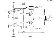
I have built (breadboarded) this amp, two monoblocks.
I’m starting to get the hang of scope use, so I tried to match the outputs of the phase splitter as close as I could. Worked fine on one amp, couldn’t get near it on the other one.
I started without the output tubes -that was easy. I could make both 1 kHz sines practically overlap completely ON BOTH AMPS.
Then with the output tubes. Got what I wanted on amp 1. On amp 2 the difference is some 50%.
I swapped tubes in every possible way, no significant difference. Plugging in the output tubes seems to mess things up. And I have no idea why. I scrutinized the layout, functionally they are exactly the same. One difference is that I used a local ground point for the entire ouput stage on the ‘bad’ amp, and on the good amp I connected cathode R and grid leaks directly to the star ground point on the regulator. But afaik that makes no difference.
Scope probes were connected to the high voltage side of the coupling cap.
I ran out of ideas. Any input would be truly appreciated.
Attachments
Grid stoppers on the EF184 screen grids might be a good idea, they are high gm tubes and HF oscillations can cause all kinds of weird problems.
Also check the CCS and the balancing pot if the ccs active components are shorted it could unbalance a lot the phase

Why are you running DC on the heaters, a needless complication?
Indirectly heated cathodes were developed more than 90 yrs ago to avoid that.
If there is PS hum at the input of this kind of amp we need to look for a more serious fault. 🙂
Indirectly heated cathodes were developed more than 90 yrs ago to avoid that.
If there is PS hum at the input of this kind of amp we need to look for a more serious fault. 🙂
The control grid of the upside down EF184 should connected to the other EF184's control grid by a 1 megohm resistor. A bypass capacitor of around 0.47mFd should be connected to the control grid of the upside down EF184's control grid and ground. Also the constant current circuit should be in series with both cathodes and ground or even a negative supply to set the operating points of this cathode coupled stage.
Last edited:
The input is appears to be at ground potential, which means that no RC is needed.
Just a grid stopper resistor to ground.
Just a grid stopper resistor to ground.
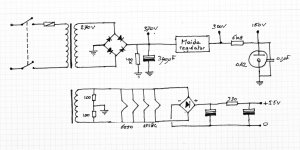
What is the + 5.5V supply for?
Did you mean - 5.5V to run the input tubes CCS? . . . (minus 5.5V).
Check the voltage polarity to the CCS.
Check the CCS, if it is bad, the input tube that is connected to the input signal connector will have more plate signal, than the other input tube plate.
You said 50% difference.
Re-check the 100k feedback resistors; the input tube 10k plate load resistors, the output transformer primary (as the earlier post-ers said).
Is the primary connected properly?
The DCR from one primary plate lead to the B+ center tap, should be close to the DCR of the other primary plate lead to the same B+ center tap.
Last edited:
Rayma,
He said it works without the output tubes in place . . .
("that was easy")
When the output tubes are "out of the socket", then . . .
If the output transformer primary's 3 leads are wired wrong, or defective, open, or shorted, . . . it will not cause the phase splitter to be significantly unbalanced.
That is because a dead short, or an open from one of the primary connections, that goes to the 100K feedback resistors will not change the phase splitter's plate load by 50%
100k in parallel with 10k = 9.09k
Open to 100k to 10k = 10k
Those are not 50% different
Check the resistors, and check the output transformer's primary and wiring, just as I said.
If I were going to Las Vegas, I would put my money on the cause of the problem to be . . .
The negative supply to the CCS
Or,
The CCS itself.
Yes, he eliminated the input stage and CCS as the problem, which was the point.
See post #6, which suggested checking the OT by substitution.
See post #6, which suggested checking the OT by substitution.
rayma,
The amount of phase splitter un-balance can be a function of the input tube's plate loads (if the CCS is less than perfect).
With 100k feedback resistors, the input plates do not see 9.09k load.
Instead, they see far less than 9.09k, because the junction of the 10k and 100k is the negative feedback node (a very low impedance).
In that case, a less than perfect CCS will have much more signal on the driven input tube; versus the un-driven input tube.
Just saying
The mysterious 5V5 supply has both a pseudo center tap to ground and a DCV output to ground. That can't be right.
All good fortune,
Chris
All good fortune,
Chris
I don't know if this has anything to do with it, but the shunt feedback in the output stage is only effective for differential signals. The coupling between both halves of the primary of the output transformer prevents it from working for common-mode signals. As a result, any imbalance between the phase splitter output voltages is made worse by the feedback.
(See https://www.diyaudio.com/community/threads/hybrid-transimpedance-tube-amp-sim.398379/post-7328403 and https://www.diyaudio.com/community/threads/hybrid-transimpedance-tube-amp-sim.398379/post-7328412 My assumption that the currents were reasonably balanced was wrong, but the feedback did make it worse.)
(See https://www.diyaudio.com/community/threads/hybrid-transimpedance-tube-amp-sim.398379/post-7328403 and https://www.diyaudio.com/community/threads/hybrid-transimpedance-tube-amp-sim.398379/post-7328412 My assumption that the currents were reasonably balanced was wrong, but the feedback did make it worse.)
What happens if you just swap the output tubes? Does the issue travel with the tubes? Could be grid current of one tube..
Could also be a leaking coupling C...
Also check your decoupling caps on the output tubes as well just in case...
Could also be a leaking coupling C...
Also check your decoupling caps on the output tubes as well just in case...
Last edited:
I checked all resistors: all OK.I would check those 100k feedback resistors. Could be a wrong value, like 10 vs 100 k.
I forgot to draw those, 1K screen stoppers.Grid stoppers on the EF184 screen grids might be a good idea, they are high gm tubes and HF oscillations can cause all kinds of weird problems.
Seems pretty clear in the schematic that I don't run the heaters with DC. I haven't said anything about hum.Why are you running DC on the heaters, a needless complication?
Indirectly heated cathodes were developed more than 90 yrs ago to avoid that.
If there is PS hum at the input of this kind of amp we need to look for a more serious fault. 🙂
I had my hopes set on the OPT, I have a few more and swapped it. Still the same issue -grrrrr...If the PI balances ok without the output tubes, it could be the OT. Can you swap those?
- Home
- Amplifiers
- Tubes / Valves
- Phase splitter output discrepancy