Is it a home made amp or a brand name? Who made it?
What is the voltage on pin 4 of the KT88s? If it's around 680 also, that is WAY TOO MUCH!
Most of the brand name 200 watt tube amps (Carlsbro, Simms-Watts, HiWatt, Sound City) use around 700 volts on the plates of the KT88s but only around 400 volts on the screens. This one change will make the KT88s bias at -50 to -55 volts. This will still be hard on the tubes but survivable. 680 on the screens will melt your tubes, especially any type that is current production.
Post a schematic if you have one.
It's a Simms-Watts, PA 200.
The transformer seems to be ultra linear. 470 Ohm in series with each G2.
I haven't managed to find a diagram for it, only the PA 100 with EL34s
The bias circuit seems fine. The dropper resistors and smoothing caps had been replaced and/or leaked/drifted. G1 coupling caps are good, voltages around the phase splitter are also good.
If the anode load resistors of the driver tube are 80-100k, the phase splitter should be a 12AX7. If they are around 47K, then it should be a 12AU7.
Only other 4-KT88 ultra-linear amp I know of is the Marshall Major which has similar voltages as yours:
http://www.drtube.com/schematics/marshall/1966u.gif
Does this look similar to how yours is wired? Notice that the tube prior to the output tubes isn't a phase splitter, it's a driver. The phase splitter is the tube before the driver tube.
I don't seem to be able to get enough drive out of an ECC83.
You may be able to use positive feedback to bootstrap the driver stage, by connecting
each of the drivers' plate resistors to the opposite phase output tube's plate.
You will likely still need a better driver tube. An example, with a cathode follower buffer:
http://www.ampslab.com/SCHEMATICS/LowRes/McIntosh_MC275.jpg
Last edited:
I don't think it would need the bootstrap if the phase splitter was run from the main HT.
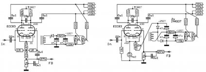
This circuit is conventional with anode loads of 100k and 82k. Their values are within tolerance.
It looks just like a phase splitter for EL34s.
So, the output tubes are new and their G2 are at the full HT, via 470 Ohm each, from the taps on the transformer. The bias circuit looks undamaged and unaltered. The only things I have changed are the dropper resistors to the PS, driver, and input stages (3 resistors, 3 capacitors). The current in the output tubes is sensible (about 40mA each). But with a bias of around -90V, the phase splitter will need to produce 180V peak-to-peak on each phase to bring the output tube G1 to near zero. I am getting just under 100V p-p from the ECC83.
Is there a tube with the same pinout as a 12AX7 that will run on a significantly higher voltage? That Marshall seems to manage with a ECC82. But is the main HT lower?
Last edited:
 moved to Instruments & Amps.
")
I don't think it would need the bootstrap if the phase splitter was run from the main HT.
Is there a tube with the same pinout as a 12AX7 that will run on a significantly higher voltage? That Marshall seems to manage with a ECC82. But is the main HT lower?
The Marshall used around 620-640 volts. It is also notorious for blowing output transformers because the output tubes have a tendency to melt-down.
Chances are that your output transformer has a primary impedance of 2300-2500 ohms. This will work well with 4 KT88s in pentode mode also.
You stated "that if the phase splitter was run from the main HT". Are there any other windings on the PT that provide a lower B+ voltage that can be used to feed the screens? 680 volts on the screens is asking for trouble, in my opinion.
The amp is working as it should. If it was originally an ultra-linear design, then Simms-Watts meant for the output tubes to not be driven with full voltage swing or it was poorly designed from the get go, which I find hard to believe as S-W made some nice stuff.
Either way, to do what you want , you're going to have to alter the amp. Why not alter it in a way which will also make it less abusive to the power tubes? Find a way to feed the screens with 400 volts. This will lower your power tube drive needs to around 100 volts, which is what you have already in the amp.
Last edited:
That mod looks interesting. The cathodes are indeed at 30V. I think all the component values are correct. But I had to change the HT droppers, because they had been changed before, and they were fried. So I don't know what their original values were, or what voltages they should have been dropping to. I set the supply for the phase splitter to 300V, because the ECC83 is rated for 300V, but I could have set it to at least 330V because the cathodes are at 30V.
Does 300V in the datasheet mean average or peak? The anodes will go quite close to the supply when fully driven, but mostly they sit at about 160V. (with 300V supply)
This is a nice modification, but it would be easier for me to change the dropper resistors if a 380V supply is OK.
The previous stage is a common cathode amplifier followed by a cathode follower, and before that are the input stages. What voltages do you suggest for these?
Last edited:
So if I split the first dropper, so it went
680V (transformer) - 400V (G2) - 330V (phase splitter) - 280V (summing amp) - 220V (input stages)
and then put suitable capacitors between the taps on the transformer and the G2 series resistors, I would have the lower voltage and the ultra linear effect as well. Or is that not how ultra linear mode works?
It may be significant that all the power tubes had been replaced.
There are no other windings on the power transformer, just HT (centre tapped) and bias (single ended).
The droppers are a chain of discrete resistors and bypass capacitors on their own little board. There is room for another section.
Last edited:
If you hook up the screens to the 400v supply, you will have to disconnect them from the screen taps of the output transformer; unfortunately you can't have it both ways.
Ultra-linear is way over-rated anyways. It sure makes the power supply a lot easier to design; I think that's why some amp companies used it.
Your voltages at the different stages sound right.
There is one problem I see if you hook up the screens like you describe... Screen grids are not a constant current consumer, they take very little current at no signal conditions, but current demand rises rapidly as power tubes are driven harder. So, in your amp, the 4 KT88s will consume less than 10ma total at zero signal but the screens will consume 60-80ma at full power output. Unfortunately, with a voltage dropping resistor string, the different voltage points will vary wildly. So you're in a catch 22 situation with your amp, unfortunately. You may want to leave the voltage dropping string alone and tap off of the main B+ supply and use a maida type HV regulator for the screens. The screens will love the regulated supply and the output stage will be quite linear.
http://www.diyaudio.com/forums/tubes-valves/209067-21st-century-maida-regulator.html
- Status
- This old topic is closed. If you want to reopen this topic, contact a moderator using the "Report Post" button.
- Home
- Live Sound
- Instruments and Amps
- phase splitter for KT88