Greetings,
good evening or good morning, depending on where you are😀
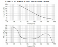
Was looking at a pretty expensive discrete Op Amp yesterday, and I found the phase gain plot to be fairly interesting:

The phase shift rolled near to 180 degrees in the middle of effective bandwidth and came back to a margin of some 70 degrees at zero crossing. This reminds me of some SPICE simulation with complicated compensation schemes, say transitional miller compensation or two pole compensation where one can actually adjust the phase to bahave like this. Also, the super feedback op amp introduced by Mr. Samuel Groner has similar behaviour, the phase already shifted more than 180 degrees(!) and then rise back.
Does anyone know if such behaviour will cause problems with stability? Havent seen this "camel back" shape in any of IC op amps..
good evening or good morning, depending on where you are😀
Was looking at a pretty expensive discrete Op Amp yesterday, and I found the phase gain plot to be fairly interesting:

The phase shift rolled near to 180 degrees in the middle of effective bandwidth and came back to a margin of some 70 degrees at zero crossing. This reminds me of some SPICE simulation with complicated compensation schemes, say transitional miller compensation or two pole compensation where one can actually adjust the phase to bahave like this. Also, the super feedback op amp introduced by Mr. Samuel Groner has similar behaviour, the phase already shifted more than 180 degrees(!) and then rise back.
Does anyone know if such behaviour will cause problems with stability? Havent seen this "camel back" shape in any of IC op amps..
Heres the link to the paper on semantic scholar:
https://pdfs.semanticscholar.org/b96c/62efa54d464b7fbb7c5bf61906e3cbb9b830.pdf
https://pdfs.semanticscholar.org/b96c/62efa54d464b7fbb7c5bf61906e3cbb9b830.pdf
Does anyone know if such behaviour will cause problems with stability? Havent seen this "camel back" shape in any of IC op amps..
This is known as conditionally stable opamps which are stable until some requirements about gain are met.
The circuit of post #1 is only close to conditional stability, for a few really conditionally stable circuits, see
Opamp with open loop gain of 1,000,000,000,000,000. 😛
Conditionally stable circuits have the reputation of bursting into uncontrollable oscillations after clipping or during start-up, but I have seen conditionally stable circuits that had no such issues and unconditionally stable circuits that did have such issues. In general, small-signal stability is no guarantee for large-signal stability; maybe the risk of getting into trouble is larger with conditionally stable circuits, but that's as far as it goes.
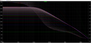
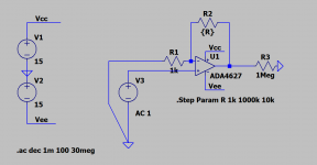
Thanks a lot for the explainations. With a simple SPICE simulation I see why those conditionally stable stuffs are stable at lower gain settings

With lower gain/higher feedback amount, the phase shift is corrected. I thought for the whole time that phase shift stays all the same, no matter what the feedback is...😱
That is very useful for making a discrete amplifier, just ignore the phase shift in the middle, then squeeze as much as you can at the zero crossing frequency😀
That is very useful for making a discrete amplifier, just ignore the phase shift in the middle, then squeeze as much as you can at the zero crossing frequency😀
Not only squeeze.
The region of interest at a fixed gain near around ULGF. Say at freqs which are +-10 dB higher and lower in gsin than ULGF you need to provide at least 180 degree, while at ULGF freq where gain = 1 you must provide at least 30 degree of safety margin regardless of load.
So you need to create fast slope where you have much of DBs, then return slope rate, naturally unbend, at around ULGF with providing some safety margin and higher than ULGF you need to bend your slope again again with some margins.
There are a much of sample designs to play with:
https://www.diyaudio.com/forums/solid-state/365685-simplicity-elegance-feedback-9.html#post6484607
Opamp + Common base
The goal of such a frequency correction is to drop achieved gain at as fast as possible rate. This allows you not to use VHF/UHF output stage and keep ULGF at a moderate ones of MHz's, maybe ten, not dozens.
🙂Wow, already something to tinker with!
Yep, the margin near the whole region of ULGF must be guaranteed otherwise bad thing will happen. And the precision of SPICE Models must be good as well, it is some fine balancing work.
My gut feeling is that, for a certain gain setting, there is always a optimum range of phase margin to be acquired through this method. If target gain is high then no need for this trick, phase shift should keep monotonic.🙄
The circuit will oscillate at any frequency where the phase shift approaches or exceeds 180 degrees and the loop gain is greater than unity.
No. Since we have a negative feedback more than one - it will ride any oscillation down.The circuit will oscillate at any frequency where the phase shift approaches or exceeds 180 degrees and the loop gain is greater than unity.
I don't understand. All I can do is repeat the Bode Stability Criterion, which says the loop gain must be less than unity when the phase equals 180 degrees. It's not good enough to have low phase margin at an intermediate frequency and then compensate it for improved margin right at the crossover frequency.
It's been a long time since I sat in an EE classroom, but maybe the problem is the Bode Criterion is typically taught in the context of dominant-pole compensation where the loop-gain declines monotonically, so stability margin also decreases with frequency.
Edit: But I admit I've forgotten enough of this theory that I don't claim to be an expert anymore. I'm open to education...
Last edited:
I'm looking at the googlez for an explanation of why conditionally-stable circuits do not oscillate. So, I admit my intuition is probably wrong, but now I need to figure out why.
now I need to figure out why.
Only unity gain freq is the region of interest in terms of gain and phase margins.
Where you have more than ~10 dB gain (or -10) phase can be any.
Thanks. This stuff is coming back to me. I recall now, the circuit is stable as long as the Nyquist plot doesn't encircle the (-1, j0) point. I just don't remember why and I'm not sure I have the patience to figure it out. It's been too long since I learned this stuff, aargh.
Sorry for the multiple posts, but when I make a mistake I'd rather figure it out than make an *** of myself insisting I'm right. I guess the point is that the circuit is only an oscillator when you have a zero in the denominator of the the closed-loop transfer function, which means the loop gain G(s)*H(s) is *exactly* minus one at 180 degrees.
I do agree it's unintuitive that a conditionally-stable circuit can still not oscillate. The problem with undergraduate EE curriculum is it necessarily doesn't cover more advanced topics in depth.
Edit: Thanks to the OP for bringing this up. I learned something this morning!
I do agree it's unintuitive that a conditionally-stable circuit can still not oscillate. The problem with undergraduate EE curriculum is it necessarily doesn't cover more advanced topics in depth.
Edit: Thanks to the OP for bringing this up. I learned something this morning!
Last edited:
You're not alone; I've designed seventh-order conditionally stable loops that are open-loop unstable and it is still counter-intuitive to me that they work, but they do. (By the way, they did need measures to make them recover from overload.)
Last edited:
Trying to tie this all up in my head -- I guess the point is a conditionally-stable amp depends on the loop gain being greater than unity at the 180 degree phase points. If it overloads, the signal gain will compress and potentially push the amp into oscillation. Ah, this explains why you sometimes see bursts of oscillation at the peaks when you push an amp to clipping.
I regret that when I graduated from college I ended up going into a career in software, so I didn't have the opportunity to keep learning this stuff in a professional setting.
-Henry
I regret that when I graduated from college I ended up going into a career in software, so I didn't have the opportunity to keep learning this stuff in a professional setting.
-Henry
It really depends on what exactly happens during clipping. If the loop gain drops while the poles and zeros of the loop gain remain where they were, then a conditionally stable amplifier will start oscillating. If clipping limits the voltage across capacitors that set the poles, a conditionally-stable third-order system effectively becomes an unconditionally-stable second- or first-order system during clipping.
Conversely, I have seen amplifiers with just one dominant pole that started oscillating at start-up or during clipping. In one case there was some weird unintended feedback via a collector-base diode of a current source transistor and a base rail that destabilized the amp as soon as the current source transistor was driven into saturation.
All in all, once you have your amplifier small-signal stable, check what happens at start up and during clipping before connecting any expensive loudspeakers, no matter whether it is supposed to be conditionally or unconditionally stable.
- Home
- Source & Line
- Analog Line Level
- Phase shift near 180° but still lots of margin?

