Hi all,
I am looking for a low frequency low power speaker (maybe 10 to 20W) that has the lowest possible phase shift for input voltage vs output pressure up to 200Hz. I am unsure about the parameters to look for.
Inductance is certainly a factor but it would only cause an electric current/magnetic field delay of a few degree at these low frequencies and low inductance values. When measuring unidentifiable (i.e. no spec sheet available) cheap speakers I am able to measure a phase shift of 90 degrees (input voltage vs output pressure) at 50Hz up to 150Hz for different speakers. This has been measured with a DC coupled electret microphone. Where do these differences come from?
If I want to find an appropriate speaker what parameters in the spec sheets do I have to take into consideration?
Thanks
Just a question:
(or three)
Isn't speaker cone motion generated by change in drive signal?
Isn't the pressure wave generated by speaker cone motion, not position?
Draw it out on a piece of paper.
What have you learned?
(or three)
Isn't speaker cone motion generated by change in drive signal?
Isn't the pressure wave generated by speaker cone motion, not position?
Draw it out on a piece of paper.
What have you learned?
You will get phase shift due to the natural resonance of the speaker and it will always be 90 degrees. If you need no phase shift down to DC that is just not possible.
Thanks for responding.
@DUG
From my understanding: Applying an AC voltage to a voice coil will cause a current to flow through it. At very low frequencies the phase shift between applied voltage and resulting current is very small, inductance would be negligible (as seen on a bode plot). The current creates a magnetic field. The magnetic field causes the voice coil and therefore the cone to move. Cone movement causes a pressure change.
For one speaker I measured a 90 degree delay between input voltage to speaker and output voltage of the electret amplifier at 50Hz. For another speaker (different model) I measured the same 90 degrees at 150Hz. The latter has almost no phase shift at 50Hz. So my guess is there must be mechanical parameters that cause this difference.
@ art West-VL
The distance between cone and microphone capsule is 1cm. Phase shift due to wavelength is negligible.
@richie00boy
can you elaborate please? Why does the phase shift between input voltage and output pressure change then?
@all
I think a good test would actually be to measure input current, not voltage. That would correspond to the voice coil current and therefore magnetic field and theoretical cone movement, wouldn't it?
Thanks again
Yes, no and maybe.
When a driver is in the mass controlled region(HF) it's acceleration and therefore pressure is related to current through the voice coil.
Below resonance where the driver is suspension controlled it's acceleration is loosely related to the signals acceleration, or in simpler terms, position is related to voltage, or for that matter current into the voice coil is acting with a force upon a spring which is the suspension according to hooke's law.
At least I think it does.
Then there is the mix of the two.
Also the fact that the driver will roll of in SPL at lower frequency will in itself cause a phase shift.
Search for miniphase to get some reading material.
You can also look up some SPICE simulation of a driver to understand it's relationship closer.
Yes, no and maybe.
When a driver is in the mass controlled region(HF) it's acceleration and therefore pressure is related to current through the voice coil.
Below resonance where the driver is suspension controlled it's acceleration is loosely related to the signals acceleration, or in simpler terms, position is related to voltage, or for that matter current into the voice coil is acting with a force upon a spring which is the suspension according to hooke's law.
At least I think it does.
Then there is the mix of the two.
Also the fact that the driver will roll of in SPL at lower frequency will in itself cause a phase shift.
Search for miniphase to get some reading material.
You can also look up some SPICE simulation of a driver to understand it's relationship closer.
Ok, that's something to digest. As for higher frequencies, I would tend to believe that a major contributor to phase shift is the inductance of the coil?
Then you say the roll-off towards DC would cause a phase shift. If we take an extreme example, like 0.1Hz (which of course I cannot measure with a microphone) then I would think there is no phase shift at all. The diaphragm would exactly follow the AC input voltage, pushing air molecules and compressing them.
Then you say the roll-off towards DC would cause a phase shift. If we take an extreme example, like 0.1Hz (which of course I cannot measure with a microphone) then I would think there is no phase shift at all. The diaphragm would exactly follow the AC input voltage, pushing air molecules and compressing them.
The amplifier's internal HPF will come into play way before you hit 1 Hz. It is common to find a woofer's phase shift below the fs. I am not sure what you are aiming for but, the components will be the limiting factor before you achieve 0.1 Hz
The amplifier's internal HPF will come into play way before you hit 1 Hz. It is common to find a woofer's phase shift below the fs. I am not sure what you are aiming for but, the components will be the limiting factor before you achieve 0.1 Hz
That was an extreme example just for better understanding. I will be working in the audible frequency range.
The amplifier can be a high power operational amplifier in the simplest case.
That was an extreme example just for better understanding. I will be working in the audible frequency range.
The amplifier can be a high power operational amplifier in the simplest case.
Well, you know what you need to do. Find a woofer that has an fs below what you consider audible frequency range to minimise any phase issues above the fs.
Good Luck!
Well, you know what you need to do. Find a woofer that has an fs below what you consider audible frequency range to minimise any phase issues above the fs.
Good Luck!
Thanks for your input but this seems kind of counter-intuitive to me. For example, adding mass to the cone would certainly lower the resonant frequency. But it would also make it more difficult for the cone to be moved because it would have more inertia. I would then expect even more phase shift. But this is something that can easily be simulated. (some more tests I can do).
Thanks
You need to understand how the speaker is reacting and that has to be measured in the actual box not simulated. Since you have not mentioned anything in regards to what woofer you are using, what is the differential of the TS Parameters (measured vs manufacture), more so cabinet, it appears you are just looking at things hypothetically.
I'm more of a buy and measure the loudspeaker in realtime type of person to know what exactly is taking place. Possibly someone can share their philosophy on the subject at hand since I a rather measure than speculate.
Good Luck!
Well, I did some measurements and was questioning the reults I couldn't understand. But your are right. I'll do some more measuring and post the results and maybe somebody is able to explain them to me. I used two different speakers for my first tests, both cheap ones with no spec sheets available. I cannot buy an appropriate speaker because I'm unsure of the parameters to look for.
Thanks for now to all for your time. I'll be back soon, with some better explanation of what I'm trying to do.
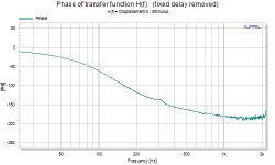
That's a typical phase transfer function of a speaker. Below resonance frequency it approaches zero. At resonance it's -90°, at higher frequencies it approaches -180°.
So my problem doesn't seem to have an easy solution. I would need to choose a speaker with a higher resonance frequency. But I want the speaker to work at low frequencies. That's a contradiction.
Attachments
The chart below shows the response of a 5" "full range" speaker in a small sealed box, an Acoustic Research "acoustic suspension" 10" speaker, a pair of Lab 12" in a sealed enclosure, and one earphone of a Sony 7506 headphone.[
So my problem doesn't seem to have an easy solution. I would need to choose a speaker with a higher resonance frequency. But I want the speaker to work at low frequencies. That's a contradiction.
In each case, as the low frequency response is extended, there is less phase change.
The speaker with the highest resonant frequency has the most phase change.
Attachments
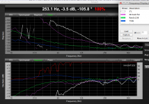
The chart below shows the response of a 5" "full range" speaker in a small sealed box, an Acoustic Research "acoustic suspension" 10" speaker, a pair of Lab 12" in a sealed enclosure, and one earphone of a Sony 7506 headphone.
In each case, as the low frequency response is extended, there is less phase change.
The speaker with the highest resonant frequency has the most phase change.
Nice software, but I'm not sure I understand the graph. If we take for example the white curve, where is the resonance frequency located? At 63Hz?
Also, I don't think I understand how the phase can change from positive through zero towards negative.
Just to make sure, I'm talking about the phase of input voltage vs cone movement. It should start at zero at very low frequencies and then a delay should be added towards higher frequencies.
The delay would depend on voice coil inductance and cone mass.
Can you explain the graph? If the phase shift goes through zero it would seem that at one part of the curves the cone movement would advance the input signal.
Thanks
Would delay be a problem? If not then you could do some FIR processing, either through a PC or a board like the MiniSHARC and correct the phase shift.
I don't recall the Fs of the 5" driver, perhaps 80-100 Hz. In box, the resonant frequency shifts up, the response is -3dB at 120 Hz and -16 at 60 Hz. The narrow peak at 63 Hz may have been caused by a wind gust.If we take for example the white curve, where is the resonance frequency located? At 63Hz?
Also, I don't think I understand how the phase can change from positive through zero towards negative.
Just to make sure, I'm talking about the phase of input voltage vs cone movement. It should start at zero at very low frequencies and then a delay should be added towards higher frequencies.
Can you explain the graph?
Phase is relative, whether the measurement starts at +180 and goes to 0, or starts at 0 and goes to -180, the same amount of "rotation" has occurred.
The input signal phase would have no rotation (it would be flat, "0") , but all speakers will show some rotation, and the rotation follows the low frequency roll off.
Last edited:
Using an accelerometer will remove the room effects and also near versus far field measurements.
Moving coil design have a particular response which is quite different from a planer type or electrostatic type.
Moving coil design have a particular response which is quite different from a planer type or electrostatic type.
Would delay be a problem? If not then you could do some FIR processing, either through a PC or a board like the MiniSHARC and correct the phase shift.
Yes , delay is a problem. Ideally the cone should be in phase with the input voltage, even though I know this is not possible. Question is how can I come near this ideal condition for frequencies up to e.g.200Hz.
As I understand so far, it is not easily doable due to the roll-off from resonance frequency towards lower frequencies. Meaning, I could take a tweeter and apply low frequency AC to it, it would probably have almost no phase shift at 200Hz due to its high Fs. But it also has extreme bad low frequency efficiency.
- Status
- Not open for further replies.
- Home
- Loudspeakers
- Subwoofers
- phase shift input voltage vs output pressure