Hello all. I'm hoping someone more knowledgeable can help me out with the electronics on my filter. I'm using a piezo tweeter in a two-way with the following filter on the piezo: a capacitor in series and a parallel (shunt) resistor across the piezo element. I'd like to know how phase is affected (if at all) by this type of arrangement. As far as I know, piezo elements also behave like capacitors in circuit.
Thanks for any help. Let me know if I should post this in a different section.
Thanks for any help. Let me know if I should post this in a different section.
The piezo looks like a capacitor. If the resistor is across the piezo (parallel to it) then everything looking into that probably just sees the resistor (presuming it's significantly lower impedance than the piezo). Then if the cap is looking into that it acts as a 1st order high pass. Phase will probably do the normal high-pass phase shift type thing.I'm using a piezo tweeter in a two-way with the following filter on the piezo: a capacitor in series and a parallel (shunt) resistor across the piezo element.
It might act something like this...
(with differences depending on the component values you used and your specific piezo.)
This is a piezo I used on a project a little while back, I measured the FR and the impedance and imported them into this software. It's XSim, I'm not sure if you're familiar with it. If you want, you could load it up and mess around with it. Here's my xsim file as pictured, I'll attach it.
The project I did with this piezo and a woofer in a 2-way is at https://www.diyaudio.com/community/threads/trying-to-get-the-best-out-of-cheapo-piezos.409639/
You can download my xsim file for the 2-way if you care to check it out, or read about what I did and how it turned out.
- A
Attachments

Thank you Adam. This is very helpful. I also read your posted link to your experiment with piezos. Especially liked the "...to sing the song of their people." 🙂
My build is using the woofer "open" (no filter). I wonder if I should add a capacitor(?) before the woofer to make its phase match that of the piezo's, if that's even sensible/feasible.
My build is using the woofer "open" (no filter). I wonder if I should add a capacitor(?) before the woofer to make its phase match that of the piezo's, if that's even sensible/feasible.
My build is using the woofer "open" (no filter). I wonder if I should add a capacitor(?) before the woofer...
You may either run the woofer unfiltered or add a suitable value of inductor in series with it (possibly in the order of 0.20 mH).
For targeted advice post the model of both piezo tweeter and woofer, plus the value of the piezo series capacitor and shunt resistor.
Note that other factors such as the offset between the acoustic centres of woofer and tweeter also affect the relative phase - it's a jungle out there!
I wonder if I should add a capacitor(?) before the woofer to make its phase match that of the piezo's, if that's even sensible/feasible.
A capacitor looking into a resistive-ish load (like a normal driver, or the piezo with the resistor across it) will let high frequencies through and block low frequencies. So you maybe want one on your piezo, and you probably don't want one on your woofer. The phase of your drivers bends along with the frequency response, so don't think of making the woofer do the same thing as your tweeter, they're opposite jobs.
You probably want to do 2, maybe 3 things:
1) Shift the level of the piezo down. You can do this with a cap in series with the piezo, but nothing else between the cap and the piezo. Or you can do this with a resistor on the "outside" of the resistor across the piezo. (when the cap sees only another cap - the piezo - it doesn't act like a filter as mentioned earlier)
2) Prevent low frequencies from getting to the piezo. The cap above does this. (the piezo will do this by itself, but a cap will help it work better)
3) Maybe block highs from getting to your woofer. This would be an inductor in series with the woofer. Possibly omit, based on desire for simplicity or wf performance...
If you wanted to be a fancy pants you could do measurements and simulations and dial it all in very precisely. If you are looking for a simpler solution you'd have to just try some things and give it a listen. You could maybe even get away with doing only item 1 from the list above (the piezo acts like a cap and naturally rejects low frequencies, to an extent), you can decide how far you want to take it.
I think Xsim is a handy tool for getting a feel for what the components will do. I'll post a simple 2-way here, I'd say play around with it to develop your understanding. But of course the actual response you'll get will depend on your specific drivers and build, what I'm posting is with driver info from my build. So develop a bit of a vibe for it with xsim until you feel like you can listen and make choices for your own build.
Note that the woofer in my build is 4 ohm nominal. An 8 ohm woofer would want caps that were smaller and inductors that were larger (by 2x). Though again, the actual details will be very dependent on the build, looking at someone else's sim is just to get a gut-feel for what is going on, detail may vary wildly... I won't be able to say much about it without knowledge of your build.
Attachments
Note that other factors such as the offset between the acoustic centres of woofer and tweeter also affect the relative phase - it's a jungle out there!
Are you talking about the z-axis offset? This would not be a problem because my woofer and piezo tweeter are physically separated - not in same enclosure. I would prefer to adjust this offset than add any filtering to the woofer. My goal is as few crossover components as possible.
Where is the acoustic center of a piezo horn in relation to the acoustic center of a traditional woofer?
"So you maybe want one on your piezo, and you probably don't want one on your woofer."
Yeah, I see my mistake. Thanks for your correction.
@djHelmoltz Post edited to remove your reply from the quote. This is a common occurrence 😉 if you get stuck with a post there is a manual editor format you can switch to.

It will depend on your specific woofer and piezo. I see you are familiar with the concept, that's good! But you will have to evaluate, I can't tell you. Have a listen...Are you talking about the z-axis offset? This would not be a problem because my woofer and piezo tweeter are physically separated - not in same enclosure. I would prefer to adjust this offset than add any filtering to the woofer. My goal is as few crossover components as possible.
Where is the acoustic center of a piezo horn in relation to the acoustic center of a traditional woofer?
Oh look, I noticed a mistake in the 2 way XO I posted. My setup used the tweeter wired out of phase, but if you make a first order setup like I started, then you'd probably want the tweeter in phase with the woofer. Ooops! But one more variable to mess with as you proceed...
Actually, no crossover components are required for a piezo tweeter to protect it from low frequencies.
This is because their impedance rises dramtically as their low end frequency response decays.
See the attached data sheet where the impedance is 450 ohms at 1 Khz.
So you can apply a full range signal directly to a piezo, as stated in the data sheet.
However, piezo's are usually much more sensitive than most woofers, so they will sound too loud without some level matching to the woofer.
This can be easily done with a simple resistive voltage divider.
Over the years I have built several 2-way speakers with piezo tweeters, no crossovers and was always pleased with the results.
Attachments
Straight attenuation might also be done using series capacitance, since this follows the impedance variation of the driver.
A piezo can be used without a crossover, but the series capacitor/shunt resistor crossover being employed by djHelmholtz is said to have the advantage of increasing the driver's power handling capacity.
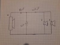
Take this Monacor piezo tweeter that extends down to 3,000 Hz and has a sensitivity of 92 dB/W/m as an example:

Monacor MPT-025
A suitable crossover and attenuation arrangement for this particular piezo would be:
A 2.2 uF series crossover cap, then a 22 ohm shunt from hot to ground, then a series cap of about 0.15 uF for 6 dB attenuation.
The basic layout is shown in the (large) attachment of a drawing made by member Databass - woofer on left, piezo(s) on right.
Take this Monacor piezo tweeter that extends down to 3,000 Hz and has a sensitivity of 92 dB/W/m as an example:
Monacor MPT-025
A suitable crossover and attenuation arrangement for this particular piezo would be:
A 2.2 uF series crossover cap, then a 22 ohm shunt from hot to ground, then a series cap of about 0.15 uF for 6 dB attenuation.
The basic layout is shown in the (large) attachment of a drawing made by member Databass - woofer on left, piezo(s) on right.
Attachments
- Home
- Loudspeakers
- Planars & Exotics
- Phase question about piezo tweeter