Or if 1n4148s as drawn then the question is what's the purpose of R78/R79 cathode resistors 10R I suppose?
Just part of bias test point. I saw it on the fender hot rod schematic.
I am sure there is some oscillation in this amp, the layout leaves something to be desired.
Also had some bad solders that contributed to the low end hum.
I built it to see if the relay controller I designed works, it will never be actively used.
Its a 3 channel PIC relay controlled guitar amp. So far the switching is spot on.
I think the fender hot rod has 1R resistor in this position, rather than 10R?
With 10R resistors, the diode(s) will prob conduct - so not much use in bias test - 1R is better?
Edit: also if 1n4148 diodes are used, forward current rating looks very tight.....and only one 6L6 flashover away from toast - higher current rated diodes might be good idea ?
With 10R resistors, the diode(s) will prob conduct - so not much use in bias test - 1R is better?
Edit: also if 1n4148 diodes are used, forward current rating looks very tight.....and only one 6L6 flashover away from toast - higher current rated diodes might be good idea ?
Last edited:
Normally when I build I put them individually on each tube with a 1ohm.
so if a tube is running hot I can bias the set based on the hottest tube.
I spoke to the tube depot and they said the match the tube a 400v plate so running higher plate voltage with start to see differences.
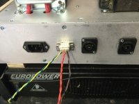
Have not found a good test point holder to so I use RCA jacks with a piece of 12g wire soldered into the whole. Run a wire from the resistor to the jack and this way you can bias the new tubes without opening up the amp.
so if a tube is running hot I can bias the set based on the hottest tube.
I spoke to the tube depot and they said the match the tube a 400v plate so running higher plate voltage with start to see differences.
Have not found a good test point holder to so I use RCA jacks with a piece of 12g wire soldered into the whole. Run a wire from the resistor to the jack and this way you can bias the new tubes without opening up the amp.