I’ve tried posting about this elsewhere and I’m hopeful someone can help me on this project. I need to invert the signal coming off a plate of one section of a 12ax7. I haven’t found the “Easy Button” for this and I’ve been reading about Interstage Transformers. I read a bunch of the threads on here I could find regarding them. It seems an IT might be the way to accomplish this needed phase flip. Here are some of my parameters and considerations:
-Available supply rail voltages are 340V, 280V, 250V, 240V.
-The 12ax7’s section has a plate resistance of ~63K w/o considering a plate resistor. With a 100k plate resistor the total is ~39K.
-Approximate idle DC current is 1.2ma for a 12ax7.
-The following stage to be driven presents about a 1meg load. (Grid/Input to a LT PI.)
-Would like about 100-3k+hz capability but I’m flexible.
This is a section I’m adding to my project guitar amp. (I hope that doesn’t disqualify my inquiry. 🙂 ) So some imperfections in the results may be completely acceptable. I need to invert the signal from this triode’s output since it eventually gets mixed in with a “dry” signal (which is otherwise out of phase with this triode’s output.) I don’t have any more triodes available and don’t want to employ any “chips” nor create any more power supplies.
The biggest decision, I guess, is do I use the primary of the IT to drive the plate or do I use a plate resistor and tap the plate to the IT with a cap. Running the DC thru the primary is fine with me but is 1.2ma of DC too “strange” for an IT? If I use the plate resistor and cap there will only be AC on the primary so perhaps a tiny audio transformer of some sort would suffice? Maybe one of those peanuts they have at Mouser would work? But their wattage ratings are so small. (I don’t know what wattage to expect from this triode but I see that the “max rating” is 1.2watts.)
Would the subject “backwards” wiring of the secondary be a problem in either approach? It seems that some ITs allow for inversion and some don’t like it?
I know that 1:1 should work but what actual winding impedance(s) would be acceptable? Should I look for windings that are close to the impedance of the triode’s plate? I’m reading about reactance and such but my head is already being stretched on this so I’m wondering if the solution is obvious and if there is an appropriate IT that’s fairly easy to get. I’ve looked at some of the Tango, Lundahl and Hammonds but I’m green. This type of tranny is not something I have a good supplier list for. Here are 2 Hammonds that perhaps would be appropriate?
109T 2watt 10k:10k 1.5ma max DC “unbalance” 300-50khz
http://www.hammondmfg.com/107.htm
126C 4watt 10k:10k 15.0ma DC rated 20-20khz 106 Henrys
http://www.hammondmfg.com/124.htm
I don’t care what it looks like nor what type of hookups or mounting it uses. If I need to shield it I’ll take care of that. Plenty of room in the chassis.
Any guidance or feedback would be greatly appreciated on this.
wtf is a dry signal?
another stage of gain will be easiest/cheapest, even if that means drilling a hole in the chassis.
another stage of gain will be easiest/cheapest, even if that means drilling a hole in the chassis.
Why not flip it at the input instead of the output? Input transformers are much smaller, cheaper, and better performing than output transformers.
"wtf is a dry signal?"
Sounds like some kind of distortion signal processing is going on and I would guess that the dry signal is the undistorted original signal. Summing its inverted form with the distorted signal would then allow one to null out the original component, leaving just the "pure" distortion.
Don
Sounds like some kind of distortion signal processing is going on and I would guess that the dry signal is the undistorted original signal. Summing its inverted form with the distorted signal would then allow one to null out the original component, leaving just the "pure" distortion.
Don
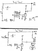
Thanx for the responses. The "dry" signal is the parallel signal path for the "normal" sound. A voltage divider is used to send a small portion of the base signal to an "effects loop." Then the 2 paths are recombined before the PI. I’ve attached a scheme of the basics of what I’m doing. The loop will allowing an echo or reverb unit to be inserted. It needs to go after the 3rd gain stage in the preamp because there is significant compression there when the volume is up. Reverb before compression doesn’t work properly here.
The signal to the effect must be brought down in strength so it doesn’t overdrive the effects unit. That’s easily done with appropriate voltage division to the wet vs. dry paths. I verified it "works" without adding the amplification to the signal returning from the effect loop. However this "wet" signal path, w/o amplification, is too quiet when recombined with the dry before the PI. This was expected since this returning signal is at instrument or line level. The dry is essentially intact at it’s strong level.
Although the signal is certainly well distorted when loud, as intended, it's the basic phase cancellation that I need to avoid that would result if I employ one triode stage to the wet path then recombine with the dry path. The scheme shows how they would be out of phase with one another. It’s possible to minimize this phase cancellation with aggressive settings on the effects unit placing the wet signal completely out of time sync since reverb/echo is a time effect. But I want to be able to eliminate all the risk of phase cancellation during less aggressive settings on the unit. And I may want to use some non-time based effect in the loop.
SY, using an input transformer sounds like a great idea! No DC current or wattage concerns. I guess I would place it before the grid of the "recovery" triode I'm adding. But I know even less about them than Interstage Transformers.
I guess something here could be appropriate:
http://www.kandkaudio.com/transformers.html
Any other links?
If I place it before the grid what would be the most appropriate 1:1 unit? I need to consider impedance or no? I don’t think I need to worry much about the amount of loading on the effect unit’s output itself since it/they should be internally buffered. That 12ax7 grid is likely to see about 1meg to ground either from the effects unit’s output or from a resistor I would place there. I don’t want to attenuate the input to the grid with a smaller resistor, if possible. I need all the output from the tube I can get. Will any particular models of these input transformers be more happy than the others to flip the phase and feed this grid? LL1690 ? LL1592 ? something else?
Thanx!!!
Attachments

Look at all the apps data on the Jensen site. Valuable reading. I commonly use the JT11P-1, but there are several other units reputed to be just as good for less money.
www.jensentransformers.com
www.jensentransformers.com
Here is a wacky idea. If the PI is LTP could one just return the effects channel to the other grid?

mashaffer, thanx for the out-of-the-box input. (I’m way out of the box with some guitar amp colleagues on this quest already.) Unfortunately, I don’t think using the “other” grid on the LTPI will work. Too bad. It’s essentially at ac ground. Mine is 5k from ac ground which is much closer than the dry path. Many setups would be very close to ac ground on that grid. The LTPI’s 2nd half is modulated via the (shared) cathode, not it’s grid. Here’s a good article on that. Scroll about half way down. That pic makes it so much easier to understand. I think it was about 10+years of messin with tube amps and reading schematics before I learned how the LTPI works.
http://www.300guitars.com/articles/article-demystifying-the-phase-inverter/
Thanx again SY. The JT11P-1 (10k:10k) and it’s sister JT-11P4-1-1 (10k:20k) are looking nice. I saw the magic words “can be reversed to invert polarity,” and the specs are great compared to my previous searches. I checked out several of the applications including inputs to 12ax7s. They show 10k-20k loads mounted across the secondary but mention “or higher” in the text. I guess that means I’m ok driving a grid with a 1meg to ground on it.
And I’m assuming that the way I’ve drawn the transformers is the simple/correct way to obtain mere phase inversion? I have not seen any drawings or applications employing a transformer to merely obtain phase inversion of a signal. I just ground one end of each winding, leaving the other connections for in and out, (and out of phase,) yes?
I don’t know if adding a tranny to the grid’s input (vs. the plate’s output) might add some noise although the shielding seems good. I drew both on the attached. Under option B, I don’t know if the 10-20k secondary is an issue. I’m thinking option B might load the plate signal down somewhat so I’m leaning towards option A.
A: Primary on buffered instrument-to-line level output from effects unit. Secondary on 1meg loaded 12ax7 grid.
B: Primary ac coupled to amplified signal from 39k plate of 12ax7. Secondary feeds LTPI that has about 1.15megs to ground on it’s grid.
Is one option clearly better than the other? Am I better off with the 10k:10k or 10k:20k ?
Attachments
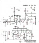
Hi Mike. Yes, I do now recall seeing that setup in the past. But it contradicts the "explanation" of how a LTPI works. 
Perhaps the 18watt's PI provides out of balance outputs. Many PIs are out of balance by design, like a cathodine, but I thought the LTPI was always somewhat close to balanced. At least in the guitar amp world. I know that many say the out of balance PI on the Tweed Deluxe is part of the magic. Maybe the 18watt's magic is also rooted in that?
The 18watt shows the same load to ground on both grids so I think each grid would provide the same gain. And that would be expected since they are employing each for each preamp channel. My problem is having only 5k to ground on my "other" grid.
I don't think I want to change the PI so dramatically since it's behavior has been fine tuned. It clips after the power tubes but before the 3rd preamp stage. This allows me to make effective use of my post phase inverter master volume control.
Thanx for the schematic and the feedback !
Hi Mike. Yes, I do now recall seeing that setup in the past. But it contradicts the "explanation" of how a LTPI works.
Perhaps the 18watt's PI provides out of balance outputs. Many PIs are out of balance by design, like a cathodine, but I thought the LTPI was always somewhat close to balanced. At least in the guitar amp world. I know that many say the out of balance PI on the Tweed Deluxe is part of the magic. Maybe the 18watt's magic is also rooted in that?
The 18watt shows the same load to ground on both grids so I think each grid would provide the same gain. And that would be expected since they are employing each for each preamp channel. My problem is having only 5k to ground on my "other" grid.
I don't think I want to change the PI so dramatically since it's behavior has been fine tuned. It clips after the power tubes but before the 3rd preamp stage. This allows me to make effective use of my post phase inverter master volume control.
Thanx for the schematic and the feedback !
jjman said:Many PIs are out of balance by design, like a cathodine,
I am anticipating a post from SY ...
LL1517
HI!
I have a question: Could I use my LL1517 (1+1 : 1+1 )
between my CDplayer and a balanced 6N6P preamp? (Something similar to the Raven preamp.) SE to PP.
I know that the LL1517 need very low source (10R) and load (600R), but maybe?
Tyimo
HI!
Why not flip it at the input instead of the output? Input transformers are much smaller, cheaper, and better performing than output transformers.
I have a question: Could I use my LL1517 (1+1 : 1+1 )
between my CDplayer and a balanced 6N6P preamp? (Something similar to the Raven preamp.) SE to PP.
I know that the LL1517 need very low source (10R) and load (600R), but maybe?
Tyimo
SY said:No need. I've disposed of that bit of folk lore on several occasions.
So I have been misled by my guitar amp buddys on the uneven outputs on a cathodine? Next I'll find out that Class A doesn't always sound better than AB 😉
As long as the loads are equal, the effective source impedance is equal at both plate and cathode. Tell your guitar buddies to put down the bong.😀
jjman said:Next I'll find out that Class A doesn't always sound better than AB 😉
Goodness, I am anticipating another post from SY ...
I don't have one of those on hand. But it would be easy to hook it up to a 10k resistor and feed it from a 100R source and see what the bandwidth and distortion look like. Is there an inductance spec for it?
- Status
- Not open for further replies.
- Home
- Amplifiers
- Tubes / Valves
- Phase flip needed -Interstage Transformer?