As a project for next year I'm going to build Pete's DCPP to be my living room hifi amp. Speakers are a pair of 8ohm Wharfedales (no idea of the sensitivity), sources will be a phono preamp (also to be built), a DAC (feed from TV) and the output from a RaspberryPi soundcard for streaming / airplay. I hope to incorporate an IR volume / input selector module and the DAC to the build.
- Pete's schematic and BOM states the use of carbon comps is necessary in certain locations. How come? Wouldn't metal filament be better?
Given this is an engineer's amp, the engineer in me is wondering why you'd consciously use CCs in the signal path (particularly grid stoppers) or anodes when MFs are cheaper / lower noise. I'm tempted to use MF throughout (power rating permitting).
- Could anyone recommend a Hammond-like chassis for the build?
The 17x10x3 looks a possibility but I'm concerned the weight of transformers could be an issue with the aluminium version. The steel version would give construction issues...
- Could anyone recommend a cheap / good quality DAC board (pre-stuffed) that could be powered from a simple regulator?
I see a few on eBay but the prices vary by a couple of orders of magnitude... All I need is an optical in.
Thanks!
It might be a matter of builder or listener preference (using carbon comps or not). The amp will certainly work with carbon films or even metal films in those locations.
These are nice chassis:
2016 New aluminum amp chassis /home audio amplifier case (Size 430*70*308MM) | eBay
Hope the link works!
I have 20 Kg of transformers on mine and zero flex.
2016 New aluminum amp chassis /home audio amplifier case (Size 430*70*308MM) | eBay
Hope the link works!
I have 20 Kg of transformers on mine and zero flex.
Attachments

Given this is an engineer's amp, the engineer in me is wondering why you'd consciously use CCs in the signal path (particularly grid stoppers) or anodes when MFs are cheaper / lower noise. I'm tempted to use MF throughout (power rating permitting).
See post #2 in this thread: http://www.diyaudio.com/forums/tubes-valves/88736-really-required-use-carbon-comp-grid-stoppers.html
jeff
Carbon comps are preferred for grid stopper applications due to their non inductive nature. I usually use common metal film resistors in non critical applications, including most grid stoppers.
TV sweep tubes and other high Gm tubes are prone to oscillation. I used carbon comps in the 3 engineers amps that I built for this reason. Would they have worked with metal film? I don't know but I decided not to find out.
I haven't tried a Hammond style chassis for an amp this big, but my guess is that it will be OK if the transformers are located near the edges of the top.
One amp was made on an aluminum plate with a wood base, one was given to my boss without a chassis, and the third is being built into a large PC case with the PC and a few other goodies......it's not done yet. That one is multi purpose. It will play music from the internal hard drives, run a recording studio style DAW (Digital Audio Workstation) and has inputs for a guitar and a MIDI keyboard. A phono stage is in the works.
All three were built according to the 125 WPC mods that I outlined in the original thread. Yeah, a PC with 125WPC for its internal sound card.........
Many thanks all.
Regarding the inductance - that is interesting. This is my first HiFi and first PCB build. The 3 guitar amps (P2P and turrets) have all worked well with only minor mods to cure oscillations. I guess with a PCB there is less room to experiment when it comes to preventing things like that... Looks like I'll stick to the tried and tested BOM!
Those chassis look nice. I keep on looking at eBay options for this. Going by Pete's top down layout view, I think there's scope for placing the trannies right at the edge.
T
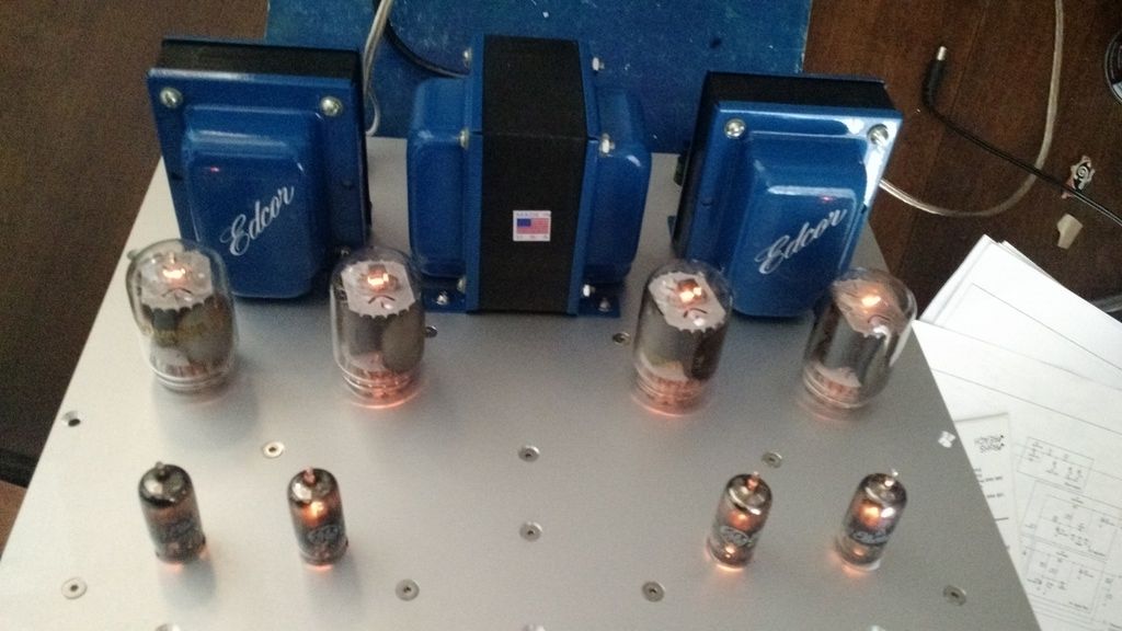
Plate is 2.5mm. The countersinks are all for #8 screws. The 2 for the mosfets should have been smaller. I'd use #6 or even #4 I I did it again as the holes in the FETs are small. I used Front Panel Express. Pricey but came out really nice.
You might check with Landfall Systems for chassis. They make a nice chassis and can fully machine it for you and have the aluminum anodized. Don't know about shipping to Oxford.
Better to read the whole thread.vinylkid58 said:See post #2 in this thread: is it really required to use carbon comp for grid stoppers?
My view is that CC resistors are not needed for grid stoppers. Almost any resistor will be sufficiently lossy to do the trick. Some people use lossy inductors instead for stoppers; what is the difference between a lossy inductor and an inductive resistor?
Better to read the whole thread.
Yes - I had the time today to go through it and also re-read Merlin's chapter on components. He does mention carbon comps having lower inductance. And Morgan Jones mentioned that carbon film also have reduced inductance and "useful as grid-stoppers". He also says "The grid-stopper must be a non- inductive resistor (carbon film is ideal)".
This link says MFs are noted for their non-inductive properties, but at the same time says at higher frequencies (>18MHz) MF have their issues: Resistors
Perhaps the physically smaller size of MFs will decrease the mutual inductance (M) to the surrounding wiring and so any increase in inductance (L) will be offset? This is above my pay-grade...
On the other hand, perhaps using MF everywhere appropriate (anodes, places where tolerance is important) apart from the few stoppers (carbon film here?) would be sensible hybrid approach given the valves being used.
Also, I have MFs in my stash and was shocked at the price Mouser are asking for them!
Tristan
Last edited:
When you build the amp -- if using Pete's (excellent) boards, remember that the tube sockets go on the non-silk side.
Pete's recommendation of the Piher potentiometers is a good one as you can adjust from either the top or bottom
When testing the amp, you don't want the boards upside down as the heat may be too much for the compactron's.
Pete's recommendation of the Piher potentiometers is a good one as you can adjust from either the top or bottom
When testing the amp, you don't want the boards upside down as the heat may be too much for the compactron's.
i use carbon comps as grid stoppers for the simple reason that i have a lot of them...
i use gage 16 aluminum for chassis, and when i see a need to reinforce,
i use aluminum angle stocks, `12 x 12 mm and 2mm thick....
the angle stocks can also be used to mount pc boards when needed
...
i use gage 16 aluminum for chassis, and when i see a need to reinforce,
i use aluminum angle stocks, `12 x 12 mm and 2mm thick....
the angle stocks can also be used to mount pc boards when needed
...
Pete's recommendation of the Piher potentiometers is a good one as you can adjust from either the top or bottom
When testing the amp, you don't want the boards upside down as the heat may be too much for the compactron's.
Thanks for the tips - I can see having to run this upside down for some time to get the balance / bias correctly dialed in. I'll watch the heat.
i use carbon comps as grid stoppers for the simple reason that i have a lot of them...
i use gage 16 aluminum for chassis, and when i see a need to reinforce,
i use aluminum angle stocks, `12 x 12 mm and 2mm thick....
the angle stocks can also be used to mount pc boards when needed
...
Thanks - my transformers arrived late last week (Edcor) and I think the weight of them will need some thought! And the evidence is to stick to stock as far as possible on this build.
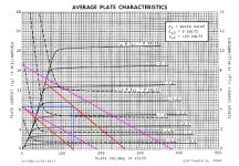
Does anyone know the input sensitivity for the DCPP?
I'd like to know the V_pp swing needed for 'full' power so I can dial in the gain level for my preamp. I have another thread here on that. Plan is for an active Baxandall tone stack and some sort of gain stage to give 3-6dB increase and allow for active balance control.
It is my firm belief that the main reason why people specify non-inductive stoppers for audio is that they have seen others specify them too. In many cases they have no experience of building RF equipment - where lossy inductors are often used as stoppers.
Close resistor tolerance is not needed in valve circuits, apart from filters. We use 1% mainly because it is difficult (and unnecessary) to buy the 10% resistors originally used for valves (or 20% in many cases). When designing valve circuitry most resistors could be selected from the E6 series - I still think in terms of E12 so it is a nuisance that many resistor ranges are sold as E48.tristanc said:On the other hand, perhaps using MF everywhere appropriate (anodes, places where tolerance is important) apart from the few stoppers (carbon film here?) would be sensible hybrid approach given the valves being used.
Does anyone know the input sensitivity for the DCPP?
IIRC, you need at least 2v to reach clipping with a stock amp.
jeff
IIRC, you need at least 2v to reach clipping with a stock amp.
Thanks Jeff - is that peak-to-peak? My estimate of the load lines for the driver stage indicates the bias set at ~-1.7V. But I may have drawn them wrong - not used to CCS...
Tristan
Attachments
voltage gain of the input differential = 1/2(gm x Rl)
gm can be seen on datasheets taking into account g1 and g2 voltages...
the 100 ohms is added to the gm...say 50 ohms per tube...
open loop gain is high, then the global feedback lowers the overall gain,
and calculation for this is over my head for now....
perhaps the tube gurus can chime in...
gm can be seen on datasheets taking into account g1 and g2 voltages...
the 100 ohms is added to the gm...say 50 ohms per tube...
open loop gain is high, then the global feedback lowers the overall gain,
and calculation for this is over my head for now....
perhaps the tube gurus can chime in...
Close resistor tolerance is not needed in valve circuits, apart from filters. We use 1% mainly because it is difficult (and unnecessary) to buy the 10% resistors originally used for valves (or 20% in many cases). When designing valve circuitry most resistors could be selected from the E6 series - I still think in terms of E12 so it is a nuisance that many resistor ranges are sold as E48.
i have seen a lot amps using 20% resistors from the olden days....
i can not complain about the sound.....
- Status
- Not open for further replies.
- Home
- Amplifiers
- Tubes / Valves
- Pete's DCPP - pre-build questions